
Patsnap Eureka
For R&D, Patsnap Eureka makes reading and utilizing patents & technical documents easy.
Patsnap Eureka AIR
Designed for self-driven R&D workflows. Generate viable solutions, solve complex R&D challenges, empower your innovation with AI.

Patsnap Eureka Materials
Designed for material experts only. Revolutionize your material R&D, from search, analyze, to developing new materials.

TechResearch
Generate reliable direction feasibility study reports for your R&D in just a few steps.

TechSeek
Discover and master advanced knowledge NOW. Basics, ideas, possibilities, all at once.

TechMind
As an expert in R&D Theories, TechMind can generates customized viable solutions instantly.

TechRisk
Analyze your overall solution with one click, know your potential R&D risks in advance.

TechMonitor
Get weekly tech updates, stay abreast of the latest tech innovations and key insights.
Optical fiber cutter
A technology of optical fiber cutter and fiber table, which is applied in the direction of optical waveguide coupling, etc., can solve the problems of human injury, difficulty in removing pain, and broken optical fiber in the human body, so as to avoid the effect of harming the human body
- Summary
- Abstract
- Description
- Claims
- Application Information
AI Technical Summary
Problems solved by technology
Method used
Image

Examples
Embodiment Construction
[0015] In order to make the purpose, technical solutions and advantages of the present invention clearer, the present invention will be further described in detail below in conjunction with the examples and accompanying drawings. As a limitation of the present invention.
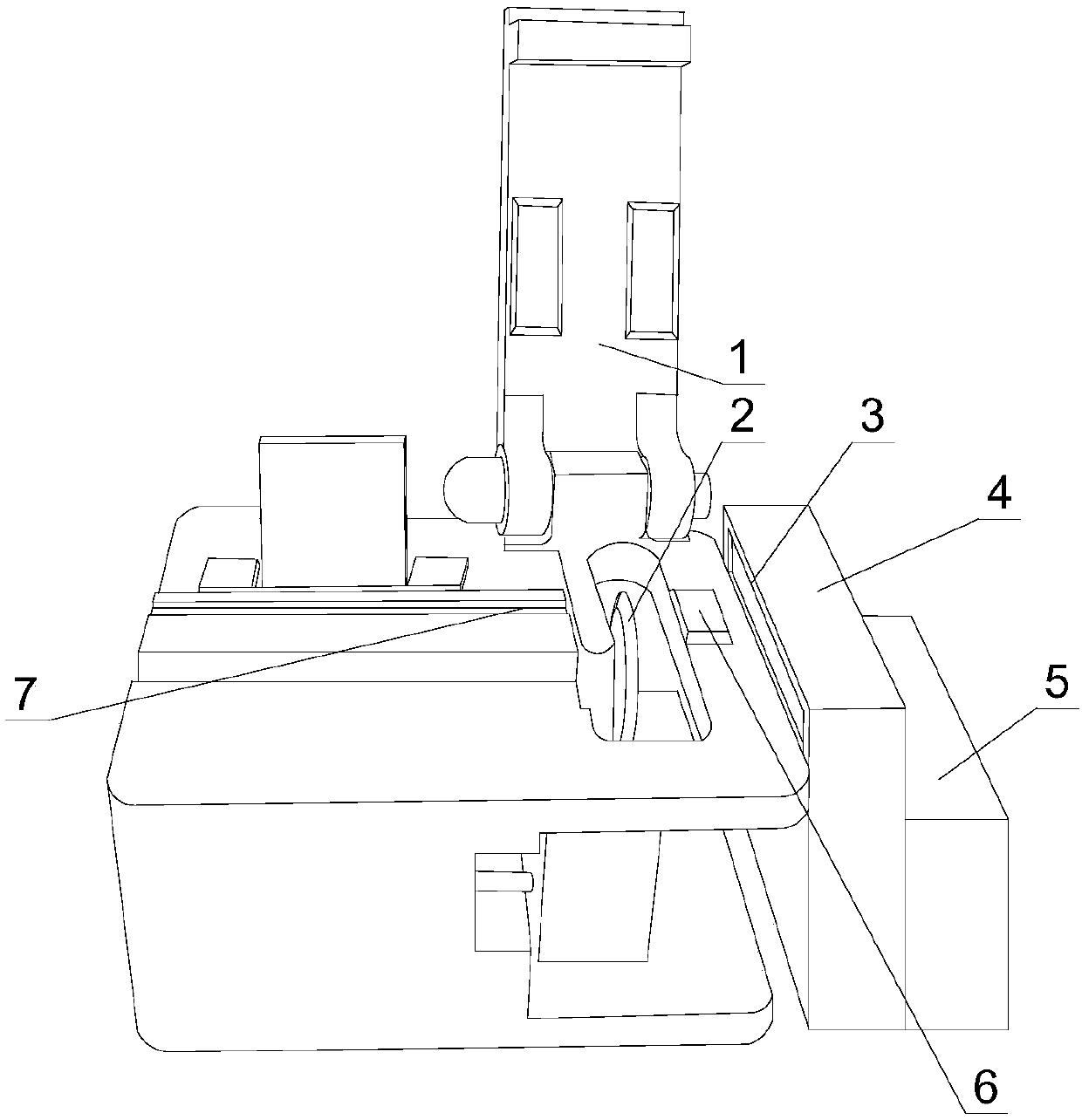
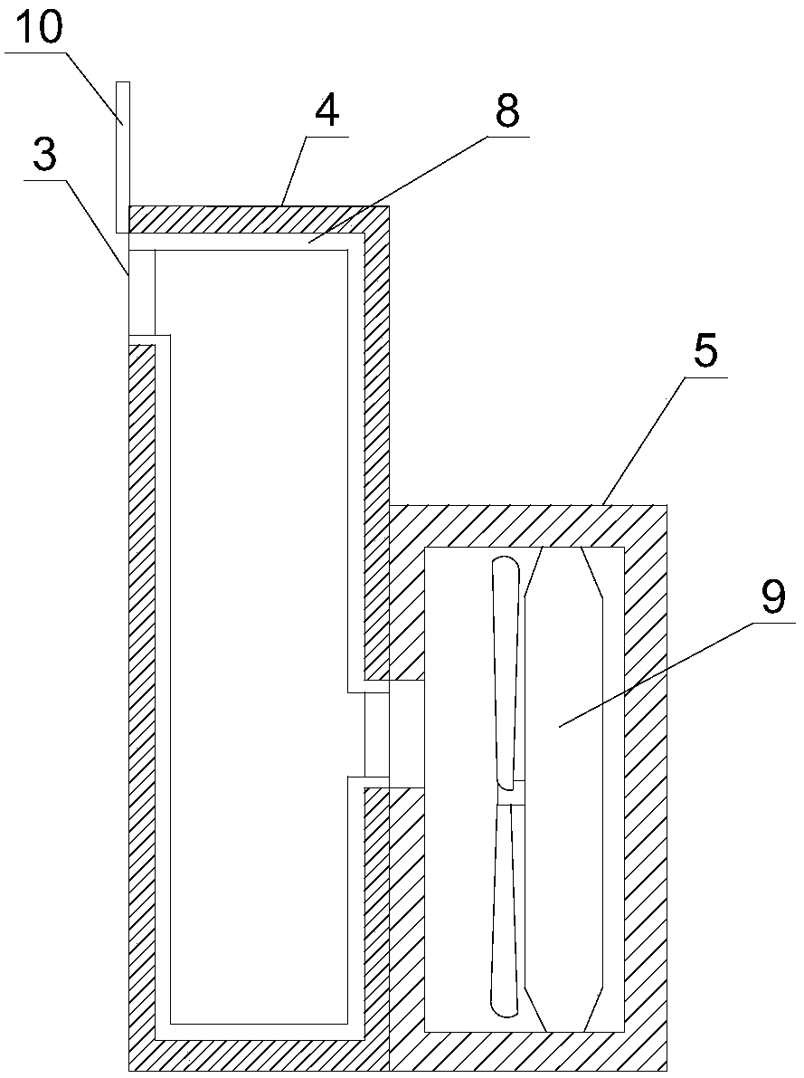
[0016] Such as Figure 1~2 As shown, an optical fiber cutter includes an optical fiber cutter, and the optical fiber cutter includes a pressing arm 1, a blade 2, a fiber pressing table 6 and a fiber-carrying groove 7, and also includes an air duct 4 and an air box 5. The duct 4 and the bellows 5 are fixed on the side of the fiber cutter, the air duct 4 is provided with an air outlet 3, and the air outlet 3 is aligned with the blade 2, the fiber press table 6 and the fiber-loading groove 7, and the bellows 5 is provided with a fan 9, the bellows 5 communicates with the air duct 4, an adhesive layer 8 is attached to the inner wall of the air duct 4, and a sliding cover 10 is provided at the air outlet 3, and ...
PUM
 Abstract
Description
Claims
Application Information
 - R&D Engineer
- R&D Manager
- IP Professional
- Industry Leading Data Capabilities
- Powerful AI technology
- Patent DNA Extraction
Browse by: Latest US Patents, China's latest patents, Technical Efficacy Thesaurus, Application Domain, Technology Topic, Popular Technical Reports.
© 2024 PatSnap. All rights reserved.Legal|Privacy policy|Modern Slavery Act Transparency Statement|Sitemap|About US| Contact US: help@patsnap.com