
Hollow fan blade-based aero-engine cooling and cooling air integrated design method

A technology for aero-engines and fan blades, applied in computer-aided design, calculation, and special data processing applications, etc., can solve problems such as pressure loss, engine efficiency drop, and cooling air pressure drop, so as to improve overall efficiency and reduce overall machine quality , the effect of reducing the gas temperature

Active Publication Date: 2018-04-13
AECC COMML AIRCRAFT ENGINE CO LTD +1
View PDF3 Cites 14 Cited by
  • Summary
  • Abstract
  • Description
  • Claims
  • Application Information

AI Technical Summary

Problems solved by technology

[0006] If the cooling air is drawn from the previous stage of the compressor to obtain a lower temperature of the cooling air, it will be accompanied by a drop in the pressure of the cooling air, which will lead to insufficient exhaust margin of the cooling air
If the external heat exchanger is used, it will not only increase the overall mass and structural complexity of the engine, but the longer flow path will also lead to greater pressure loss, which is also not conducive to ensuring the flow of cold air in the turbine blades
The current engine cooling air accounts for more than 20% of the total flow of the core engine. If the cooling air temperature cannot be effectively reduced, it is necessary to rely on increasing the cooling air flow to ensure the cooling of the turbine, which will lead to a decrease in engine efficiency.

Method used


Image

  • Hollow fan blade-based aero-engine cooling and cooling air integrated design method
  • Hollow fan blade-based aero-engine cooling and cooling air integrated design method
  • Hollow fan blade-based aero-engine cooling and cooling air integrated design method

Examples


Embodiment Construction

[0031] The present invention will be further described below in conjunction with accompanying drawings and examples.

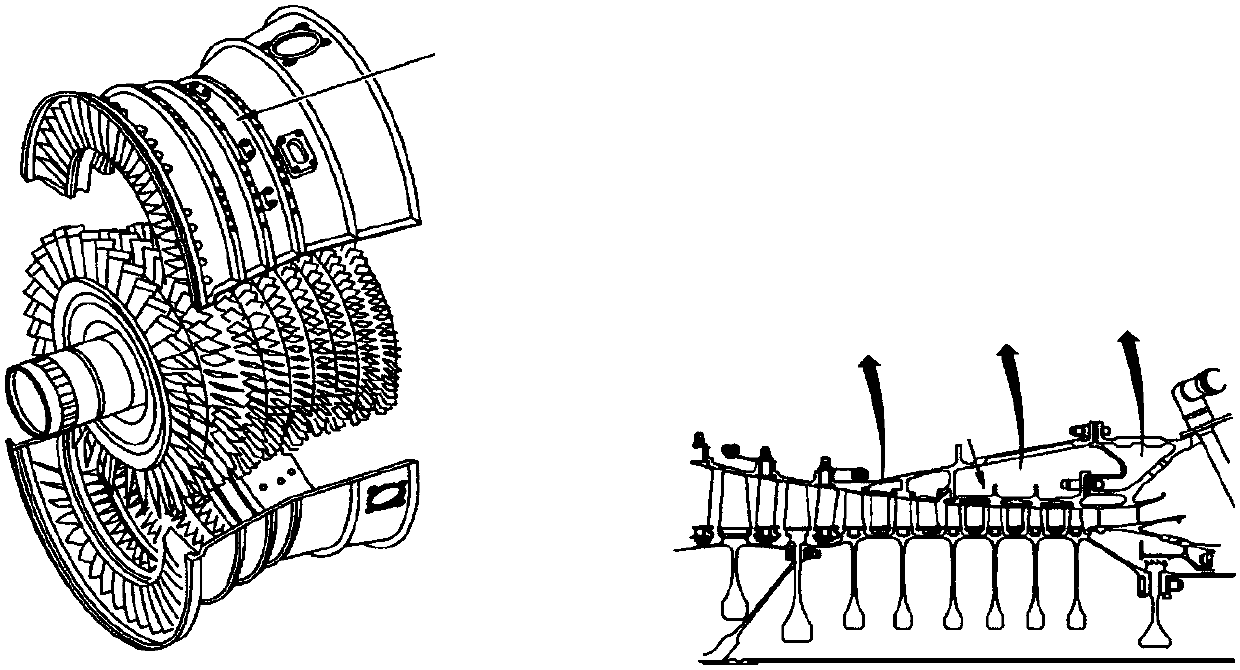
[0032] The invention provides a structural integration design method of cooling and cooling air of an aeroengine based on a hollow fan. Through low-pressure and high-pressure compressors, the intake air of the engine is led to the fan 3 to cool and pressurize the air, and the air intake components are Anti-icing, then through the fan 3, the outer casing 4 and the outer casing bracket, reaches the core machine and the combustion chamber to realize the cooling of the turbine.

[0033] like Figure 4 As shown, the air-core fan-based aero-engine cooling of the present invention and the structural integration design method of cooling air are specifically completed through the following steps:

[0034] Step 1: Bleed air from a given bleed air position at the end of the high-pressure compressor, flow to the intake cone through the compressor shaft-disc cavity channe...


PUM


Abstract

The invention discloses a hollow fan blade-based aero-engine cooling and cooling air integrated design method, and relates to the technical field of aero-engine design. The design method comprises thesteps of introducing air to an air inlet cone from an air introduction position given by an air compressor, and heating the air inlet cone by utilizing the introduced air to prevent ice; performing centrifugal pressurization and cooling by a channel in a fan, collecting the pressurized air from a fan case, passing a cooling channel of an external case and an external case support plate in sequence to reach a core engine, and continuing to backwards lead the air to the outer side of a turbine combustion chamber; and enabling the air to flow in a turbine stator, and cooling a guide blade and stator and rotor parts. According to the method, the design idea that the air passes a turbine after passing the fan is adopted; ice prevention and turbine blade cooling of an air inlet system can be considered at the same time; excessive parts do not need to be added, so that the mass of the whole engine is reduced; and the cooling air quality and the overall engine efficiency are improved.

Description

technical field [0001] The present invention relates to the technical field of integrated design of aero-engine cooling and cooling air. Specifically, it proposes an integrated design method for air intake anti-icing and turbine cooling based on hollow fan blades for turbofan engines. The air between the compressor stages is led into the fairing, and then led to the turbine for cooling after being centrifugally boosted by the inner channel of the fan, which realizes the improvement of the cooling and cooling air of the turbofan engine, especially suitable for the application of hollow fan blades Cooling and cooling air design for turbofan engines. Background technique [0002] In the field of aero-engine development, under the background of pursuing low fuel consumption and high thrust-to-weight ratio, the pressure ratio of the compressor and the temperature before the turbine continue to increase, but the ability of the turbine blades to withstand high temperatures is limit...

Claims


Application Information

Patent Timeline
IPC IPC(8): G06F17/50
CPCG06F30/17G06F2111/10G06F2119/08
Inventor 邓宏武李利昂田淑青
Owner AECC COMML AIRCRAFT ENGINE CO LTD
Learn More