
Control system of peak value current type cuk switch converter

A switching converter and control system technology, applied in the field of microelectronics, can solve the problems of low loop gain and poor adjustment ability, achieve high loop gain, simple and effective compensation network, and improve the effect of load modulation rate

Inactive Publication Date: 2018-04-13
NANJING GUOZHAO OPTOELECTRONICS TECH CO LTD
View PDF2 Cites 5 Cited by
  • Summary
  • Abstract
  • Description
  • Claims
  • Application Information

AI Technical Summary

Problems solved by technology

[0004] The purpose of the present invention is to design a peak current type cuk for the problems of low loop gain and poor adjustment ability in the existing cuk type switching converter with single-cycle control, which are not suitable for occasions requiring high output voltage accuracy. The control system of the switching converter, so that the loop constitutes a closed-loop control system, and the cuk-type switching converter is kept stable by compensating the zero-pole point of the power stage

Method used


Image

  • Control system of peak value current type cuk switch converter
  • Control system of peak value current type cuk switch converter

Examples


Embodiment Construction

[0016] The present invention will be further described below in conjunction with drawings and embodiments.

[0017] Such as Figure 1-2 shown.

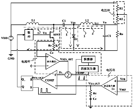
[0018] A control system of a peak current type cuk switching converter, which includes a cuk type switching power supply power stage circuit, a voltage loop control circuit, a current loop control circuit, and a duty cycle generation circuit. Such as figure 1 shown. in:

[0019] The cuk type switching power supply power stage circuit includes input inductor L1, output inductor L2, input capacitor C1, output capacitor C2, power tube MN1, freewheeling diode D1, load resistor Ro and feedback resistor string R1, R2. One end of the input inductor L1 is connected to the power supply voltage VDD, and the other end is connected to one end of the input capacitor C1 and the drain of the power transistor MN1; the other end of the input capacitor C1 is connected to one end of the output inductor L2 and the forward end of the freewheeling diod...


PUM


Abstract

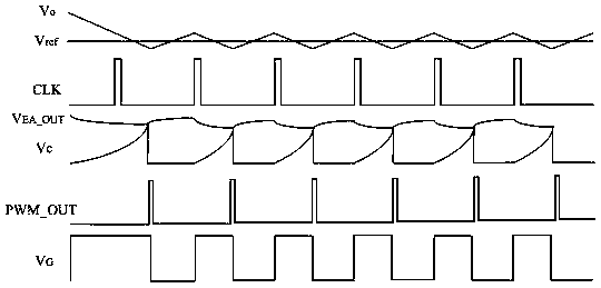
A control system of a peak value current type cuk switch converter is characterized in that the system includes a cuk type switch power source power level circuit, a voltage loop control circuit, a current loop control circuit and a duty ratio generation circuit; the voltage loop control circuit acquires signals VEA_OUT through detecting error signals of output voltage Vo and reference voltage VREF; the current loop control circuit acquires Vc through detecting and adding power tube current VSEN_OUT and slope signals VRAMP together; the duty ratio generation circuit compares VEA_OUT with Vc and thus generates duty ratio signals for controlling the switching on and switching off of a power tube MN1 of a cuk type switch power source. The invention can provide comparatively high loop gain, can effectively improve system load modulation rate and a compensation network is simple and effective.

Description

technical field [0001] The invention relates to the technical field of microelectronics, in particular to a DC-DC switching power supply, in particular to a control system of a peak current type cuk switching converter inside a Yide integrated circuit. Background technique [0002] Organic Light Emitting Diode OLED (Organic Light Emitting Diode OLED) has the characteristics of softness, transparency, clear picture quality, energy saving and environmental protection, and is regarded as the most promising next-generation flat-panel display technology. In order to maximize the brightness of light emission, the cathode of the OLED display needs a negative voltage for power supply, so the design of negative voltage chips has become the mainstream trend in this field. The cuk circuit adopts DC chopper technology, which has the characteristics of low output current ripple, which also makes the cuk converter have a wide application prospect in occasions with high requirements on rip...

Claims


Application Information

Patent Timeline
Patent Type & Authority Applications(China)
IPC IPC(8): H02M3/157
CPCH02M3/157
Inventor 秦昌兵陈啟宏张白雪
Owner NANJING GUOZHAO OPTOELECTRONICS TECH CO LTD
Learn More