Wireless communication device based on distributed optical resonant cavity
A wireless communication device and optical resonant cavity technology, applied in short-distance systems, electrical components, transmission systems, etc., can solve problems such as difficult aiming, communication interruption, and complicated operation, and achieve high safety, low interference, and equipment The effect of simple structure
- Summary
- Abstract
- Description
- Claims
- Application Information
AI Technical Summary
Problems solved by technology
Method used
Image

Examples
Embodiment 1
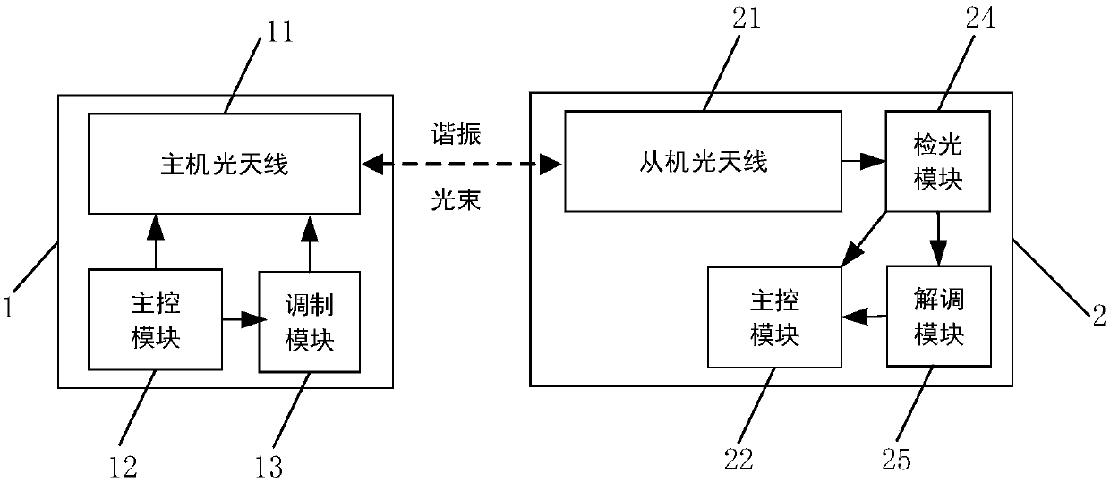
[0111] Embodiment 1: Directly pumped 113-modulated unidirectional communication device
[0112] This embodiment provides an example to demonstrate a one-way communication device that directly modulates the pump 113. The structure of the communication device is Figure 14 As shown, the master 1 includes a master optical antenna 11, a master master control module 12, and a master modulation module 13, and the slave 2 includes a slave optical antenna 21, a slave master control module 22, a slave detection optical module 24, and a slave demodulation The module 25, the master optical antenna 11 and the slave optical antenna 21 constitute an optical resonant cavity, and a resonant beam is formed in the optical resonant cavity. The modulation method of the device is that the modulation module directly drives the pump 113 to directly modulate the light generation process. The intensity can be adjusted by controlling the input power, so intensity modulation, switch keying, intensity keyi...
Embodiment 2
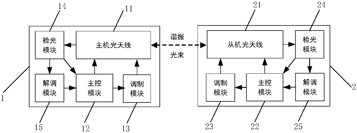
[0113] Embodiment 2: Directly pumped 113 modulated two-way communication device without optical path monitoring and control
[0114] This embodiment provides an example to demonstrate a direct pump 113 modulation communication device without optical path monitoring and control. The structure of the device is as Figure 15 Shown. Host 1 includes a host optical antenna 11, a host main control module 12, a host modulation module 13, a host optical detection module 14 and a host demodulation module 15, and a slave 2 includes a slave optical antenna 21, a slave master control module 22, and a slave modulation module. Module 23, slave optical detection module 24 and slave demodulation module 25. The host optical inspection module 14 and the slave optical inspection module 24 both use a photoelectric probe E3.
[0115] The modulation method of the communication device is that the host modulation module 13 directly drives the pump 113 to directly modulate the light generation process. T...
Embodiment 3
[0116] Embodiment 3: Host 1 direct pump 113 modulation two-way communication device with optical path monitoring and control
[0117] This embodiment provides an example to demonstrate that the host 1 has a direct pump 113 modulated two-way communication device with optical path monitoring and control. The structure of the device is as Figure 16 Shown. Host 1 includes a host optical antenna 11, a host main control module 12, a host modulation module 13, a host optical detection module 14 and a host demodulation module 15, and a slave 2 includes a slave optical antenna 21, a slave master control module 22, and a slave modulation module. Module 23, slave optical detection module 24 and slave demodulation module 25. The host optical inspection module 14 and the slave optical inspection module 24 both use a photoelectric probe E3, and the host 1 also sets a photosensitive array E1 for optical path monitoring.
[0118] The modulation method of the communication device in this embodim...
PUM
 Abstract
Description
Claims
Application Information
 - R&D
- Intellectual Property
- Life Sciences
- Materials
- Tech Scout
- Unparalleled Data Quality
- Higher Quality Content
- 60% Fewer Hallucinations
Browse by: Latest US Patents, China's latest patents, Technical Efficacy Thesaurus, Application Domain, Technology Topic, Popular Technical Reports.
© 2025 PatSnap. All rights reserved.Legal|Privacy policy|Modern Slavery Act Transparency Statement|Sitemap|About US| Contact US: help@patsnap.com