

Special air compressor system for supplying air to constant-pressure air storage source
An air compressor and air source technology, applied in mechanical equipment, engine components, machines/engines, etc., can solve problems such as low compression efficiency and fluctuations in air supply pressure, so as to improve compression efficiency, reduce complexity, and save manufacturing costs. Effect
- Summary
- Abstract
- Description
- Claims
- Application Information
AI Technical Summary
Problems solved by technology
Method used
Image

Examples
Embodiment Construction
[0022] The embodiments will be described in detail below in conjunction with the accompanying drawings.
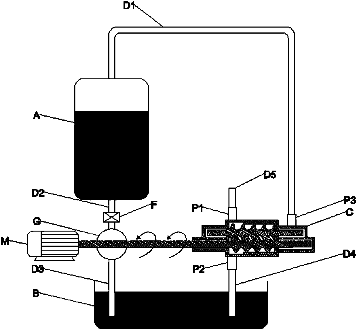
[0023] figure 1 Schematic diagram of a dedicated air compressor system for supplying air to a constant-pressure gas storage source. The motor M, the water turbine G, and the screw air compressor C are coaxially connected, and the rotation speed of the three is the same. Connect with screw air compressor C. In the initial state, the pressure vessel A is filled with water and there is no compressed air. With the injection of compressed air, an equal volume of water is discharged to the water turbine, which drives the water turbine G and the screw air compressor C to rotate coaxially. The air is mixed and compressed, and then transferred to pressure vessel A, where the mixture of compressed air and water realizes gas-liquid separation. The system uses the flow valve F to control the water output of the pressure vessel A to ensure that the water output is equal to the intake...
PUM
 Abstract
Description
Claims
Application Information