
Optical fiber diffuse transmission probe for spectral non-destructive detection of solid particles

A solid particle, non-destructive detection technology, applied in the field of near-infrared spectral analysis, can solve the problems of small optical path, unsuitable for the detection of solid particles such as grain, etc., and achieve the effect of improving the efficiency of detection

Inactive Publication Date: 2018-04-17
广东星创众谱仪器有限公司
View PDF5 Cites 1 Cited by
  • Summary
  • Abstract
  • Description
  • Claims
  • Application Information

AI Technical Summary

Problems solved by technology

However, the grain particles are large, and a larger optical path is required to make the transmitted light more uniform. The current transmission probe has too small optical path and is not suitable for the detection of solid particles such as grain.

Method used


Image

  • Optical fiber diffuse transmission probe for spectral non-destructive detection of solid particles
  • Optical fiber diffuse transmission probe for spectral non-destructive detection of solid particles
  • Optical fiber diffuse transmission probe for spectral non-destructive detection of solid particles

Examples


Embodiment 1

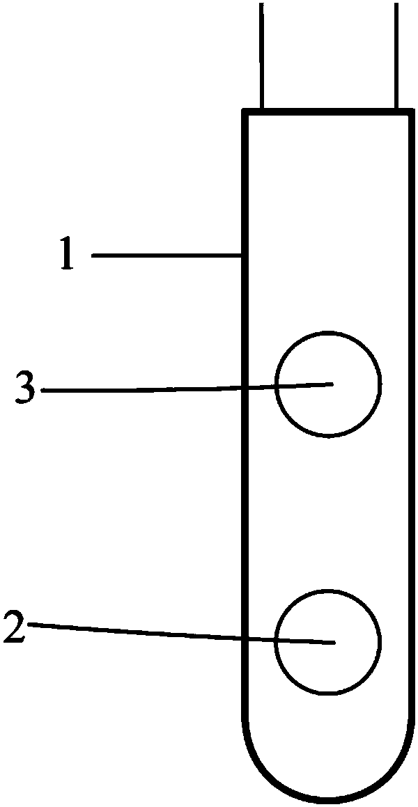
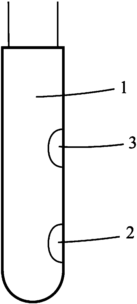
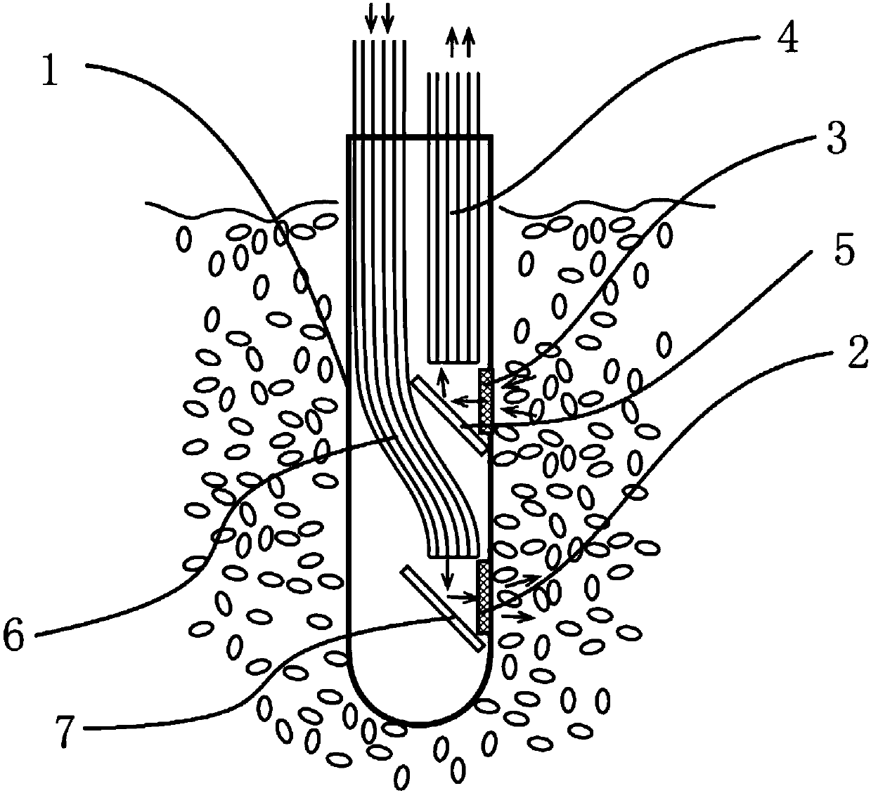
[0034] Such as figure 1 , 2 , 3, 5, a kind of optical fiber diffuse transmission type probe that is used for the non-destructive detection of solid particle spectrum, comprises casing, exit window, entrance window, exit light emitting device, incident optical fiber bundle, first reflector, wherein exit window, entrance window Installed on the same side of the housing and facing the same direction, the outgoing light emitting device guides the outgoing light to the exit window and enters the solid particles, and the diffuse transmitted light formed by the outgoing light passes through the solid particles and enters through the entrance window to obtain the incident light. The incident light passes through the first A mirror redirects the exit into the incident fiber bundle.

[0035] The outgoing light emitting device includes a first light source, an outgoing optical fiber bundle, and a second reflector, wherein the outgoing optical fiber bundle transmits the light from the fi...

Embodiment 2

[0042] Such as figure 1 , 2 , 4, 5, the difference between embodiment 2 and embodiment 1 is: the outgoing light and the incident light are not all conducted using fiber bundles; in embodiment 2, the incident light is conducted using optical fiber bundles, and the outgoing light is not conducted using fiber bundles. Two light sources are integrated inside the probe.

[0043] The outgoing light emitting device includes a second light source, the second light source is placed in the casing and faces the exit window, and the light emitted by the second light source directly enters the solid particles through the exit window.

[0044] The spectrum of the second light source is 600-1100 nm, and the second light source is a tungsten halogen lamp or an LED light source whose spectrum is continuously distributed within the range of 600-1100 nm.

[0045] The first reflector is a plane reflector or a solid right-angle prism with a long side coated with a reflective film.

[0046] The ...


PUM


Abstract

The invention discloses an optical fiber diffuse transmission probe for spectral non-destructive detection of solid particles. The probe comprises a shell, an emitting window, an incidence window, anemergent light emitting device, incidence optical fiber bundles and a first reflection window; the emitting window and the incidence window are installed at the same side of the shell and face the same direction, the emergent light emitting device transmits emergent light to the emitting window, the emergent light enters the solid particles, diffuse transmission light formed by the emergent lightpassing through the solid particles enters the incidence window, and incidence light is obtained and enters the incidence optical fiber bundles to be transmitted out after the direction of the incidence light is changed by the first reflection mirror. Compared with existing transmission and diffuse reflection detection modes, the diffuse transmission probe has the advantages that sample pools areomitted, sampling, loading and other operation are not needed, the use is more convenient, and the detection efficiency is higher.

Description

technical field [0001] The invention relates to the field of near-infrared spectrum analysis, in particular to an optical fiber diffuse transmission probe used for spectral non-destructive detection of solid particles. Background technique [0002] It is of great significance to quickly detect some composition information of solid particles such as grain, oil crop seeds, and feed particles. For example, obtaining information on the content of some ingredients in grains and other crops is of great significance in the stages of harvesting, purchasing, storage, transportation, and processing of grains. Content information to adjust production. [0003] Near-infrared spectral analysis technology uses near-infrared light to detect material components. Using this technology to detect solid particles such as grain does not require reagents, does not damage samples, and is fast and accurate. This technology has been widely used in developed countries such as the United States sinc...

Claims


Application Information

Patent Timeline
IPC IPC(8): G01N21/3563G01N21/359G01N21/01
CPCG01N21/01G01N21/3563G01N21/359G01N2021/0112G01N21/8507
Inventor 王动民丁海泉高洪智于新洋苏建全
Owner 广东星创众谱仪器有限公司
Learn More