
Method for correcting oil saturation based on liquid drainage phenomenon through oil-liquid ratio of rock core sidewall

A technology of saturation and core, which is applied in the field of correcting oil saturation by using the oil-liquid ratio of the core side wall during the coring period based on the liquid drainage phenomenon, which can solve problems such as swelling, oil and water liquid loss, and difficult correction of pore changes, and achieve Clear technical thinking, good operability, simple application effect

Active Publication Date: 2018-04-17
CHINA PETROLEUM & CHEM CORP +1
View PDF4 Cites 4 Cited by
  • Summary
  • Abstract
  • Description
  • Claims
  • Application Information

AI Technical Summary

Problems solved by technology

[0003] 1. There are many factors causing the error of core oil saturation, and it is not feasible to directly correct each factor. For example, because the core needs to be stored in a -80°C freezer for several months, the water freezes into ice, causing the pores to freeze and crack. , the resulting pore change is actually difficult to correct; in addition, the volatilization of oil and water from core cutting and the volatilization of oil and water from long-term placement of cores are also difficult to correct directly;
[0004] 2. At present, there are still geometric or mathematical methods for the correction of core saturation, but there are still some problems, for example, there is no obvious relationship between the angle offset method and the error generation factors, and the solution method of the transcendental equation is very cumbersome;
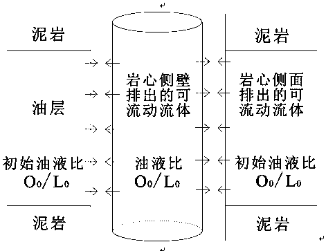
[0005] 3. After the core is taken out, the volume of dissolved gas in the crude oil will expand significantly, driving out the oil-water mixture in the core, and the core can also flow out directly after being out of the cylinder, resulting in a large loss of oil and water liquid;

Method used


Image

  • Method for correcting oil saturation based on liquid drainage phenomenon through oil-liquid ratio of rock core sidewall
  • Method for correcting oil saturation based on liquid drainage phenomenon through oil-liquid ratio of rock core sidewall
  • Method for correcting oil saturation based on liquid drainage phenomenon through oil-liquid ratio of rock core sidewall

Examples


Embodiment Construction

[0020] In order to make the above and other objects, features and advantages of the present invention more comprehensible, the preferred embodiments are listed below and shown in the accompanying drawings in detail as follows.

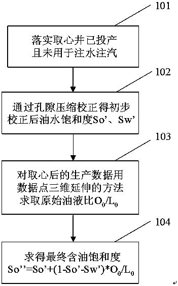
[0021] Such as figure 1 as shown, figure 1 It is a flow chart of the method for correcting oil saturation by core sidewall oil-liquid ratio based on liquid drainage phenomenon of the present invention.

[0022] Step 101, according to the production data of the oil area, confirm that the coring wells that need data processing or the adjacent wells have been put into production, and have oil production and liquid production data; it is also necessary to confirm that the core sealing rate is up to standard, and the coring wells have been put into production It means that oil production has started, and it has not been used for water injection or steam injection.

[0023] Step 102, for this type of coring well, the porosity overburden pressure correction...


PUM


Abstract

The invention provides a method for correcting the oil saturation based on a liquid drainage phenomenon through the oil-liquid ratio of a rock core sidewall, and the method comprises the steps: 1, determining a coring well, the data of which needs to be processed according to the production data of an oil field, or confirming that an adjacent well is put into production, wherein there is oil production and liquid production data; 2, carrying out the porosity compression correction of the rock core saturation, and obtaining the rock core oil saturation and water saturation after initial correction; 3, obtaining the proportion of initial discharged liquid crude oil through the solving of the original oil-liquid ratio; 4, obtaining the corrected oil saturation through the rock core oil saturation and water saturation after initial correction at step 2 and the original oil-liquid ratio obtained at a coring moment at step 3. The method provided by the invention is better in operability, isinnovative and practical, is easy for popularization, and provides a new feasible method for the correction of the oil saturation of the rock core.

Description

technical field [0001] The invention relates to the technical field of oilfield exploration and development, in particular to a method for correcting oil saturation by using the oil-liquid ratio of the side wall of the core during the coring period based on the liquid drainage phenomenon. Background technique [0002] At present, the factors causing the core oil saturation error are complex and diverse, there are many mathematical correction methods, and there are many auxiliary correction data available: [0003] 1. There are many factors causing the error of core oil saturation, and it is not feasible to directly correct each factor. For example, because the core needs to be stored in a -80°C freezer for several months, the water freezes into ice, causing the pores to freeze and crack. , the resulting pore change is actually difficult to correct; in addition, the volatilization of oil and water from core cutting and the volatilization of oil and water from long-term placem...

Claims


Application Information

Patent Timeline
Patent Type & Authority Applications(China)
IPC IPC(8): G06Q50/02
CPCG06Q50/02
Inventor 吴兆徽刘西雷牛丽娟李伟忠吴光焕李伟翟麟秀吴颖昊韦涛崔卫东路言秋赵衍彬杨鹏安洁陈明铭宿文浩梁金萍孙钰马健李珊珊王传飞
Owner CHINA PETROLEUM & CHEM CORP
Learn More