High frequency transformer

A technology of high-frequency transformers and transformers, applied in the field of high-frequency transformers, can solve problems such as dust and water vapor entering the transformer, affecting the normal operation and service life of the transformer, and achieve better convection effect, good heat dissipation effect, and simple operation.

Active Publication Date: 2019-06-14
苏州扬麒电子工业有限公司
View PDF4 Cites 2 Cited by
  • Summary
  • Abstract
  • Description
  • Claims
  • Application Information

AI Technical Summary

Problems solved by technology

[0006] However, the above-mentioned technical solution still has certain defects: external dust, water vapor, etc. can easily enter the inside of the transformer through the cooling holes, affecting the normal operation and service life of the transformer.

Method used


Image

  • High frequency transformer
  • High frequency transformer
  • High frequency transformer

Examples


Embodiment 1

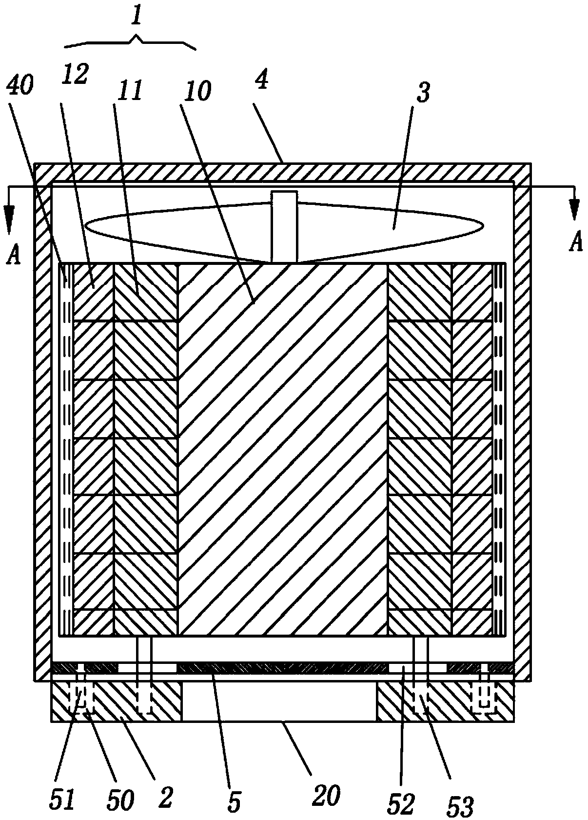
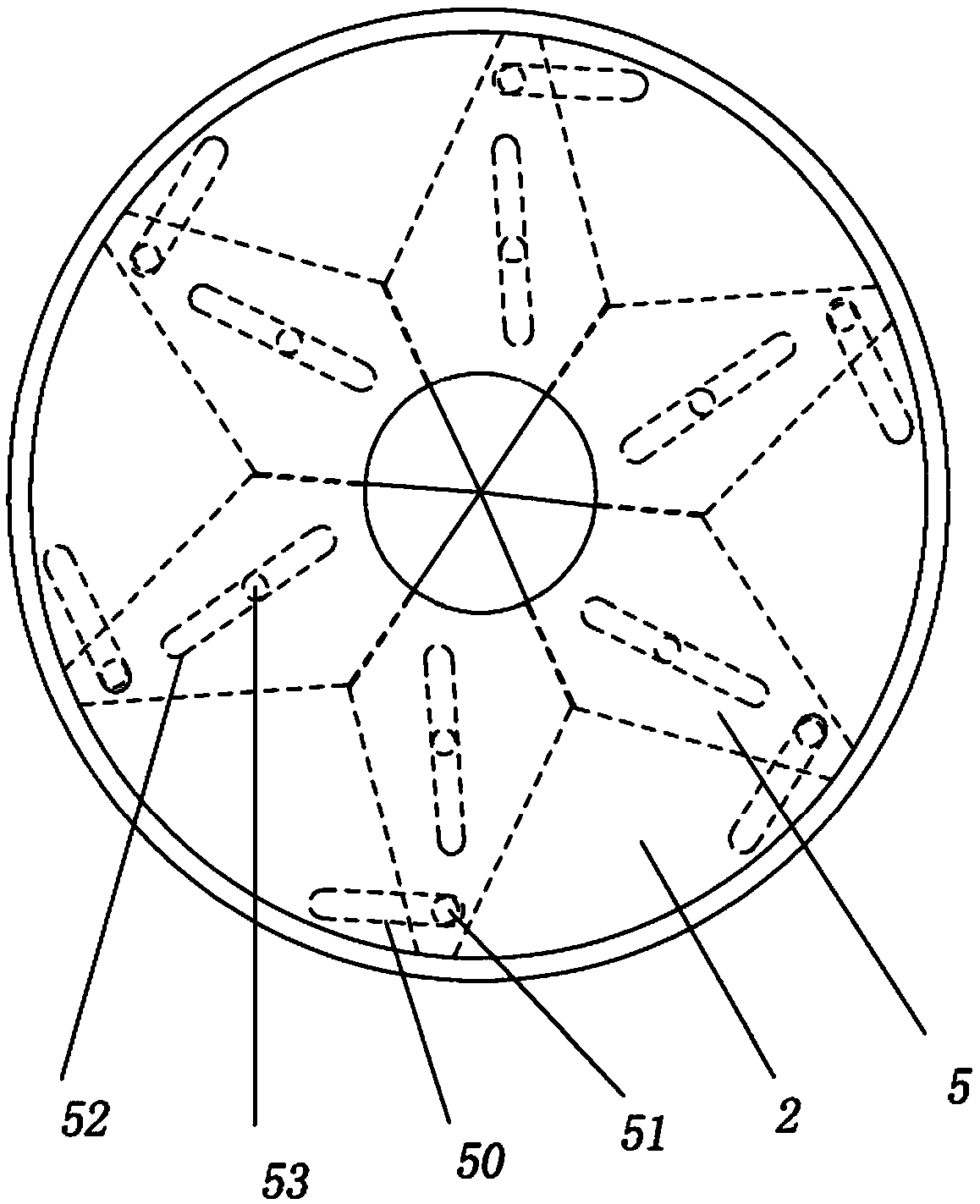
[0026] The embodiment is basically as attached figure 1 Shown: a high-frequency transformer, including a transformer main body 1, a bottom plate 2 and a cooling fan 3, and also includes a sealing cover 4, the longitudinal section of the sealing cover 4 is inverted U-shaped; the transformer main body 1 includes a cylindrical iron core 10 and is wound on Coils on the iron core 10; each set of coils includes an inner primary coil 11 and an outer secondary coil 12; the transformer main body 1 is located in the sealed cover 4, the cooling fan 3 is located on the top of the transformer main body 1, and the bottom plate 2 is located on the transformer main body 1, the sealing cover 4 and the bottom plate 2 are rotationally connected, and the sealing cover 4 and the bottom plate 2 are hermetically connected. Such as Figure 4 As shown, a hollow ventilation pipe 40 is provided around the transformer main body 1 , one end of the ventilation pipe 40 is located at the top of the transfor...

Embodiment 2

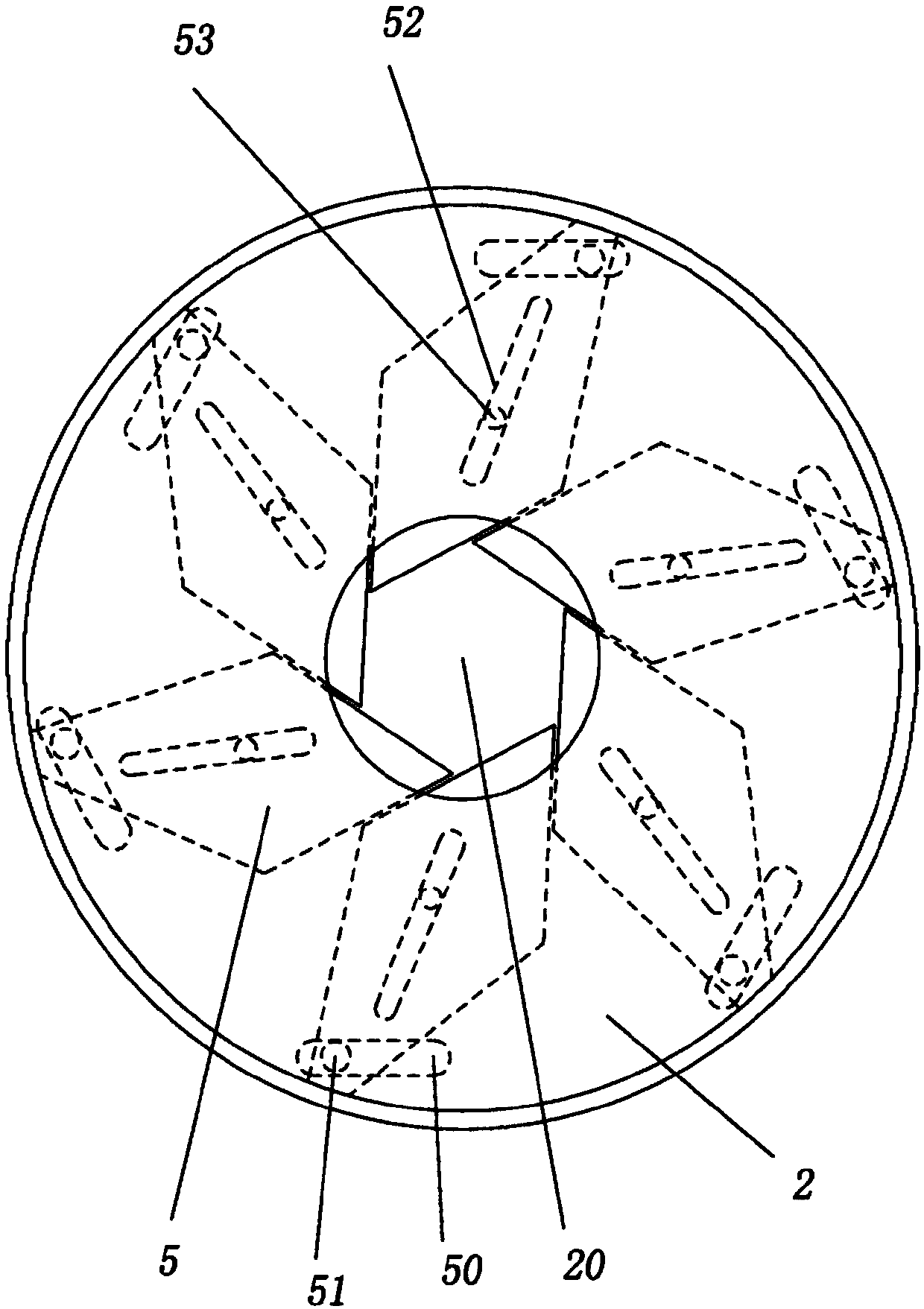
[0030] as attached Figure 5 And attached Figure 6 As shown, the difference between this embodiment and Embodiment 1 is that the number of opening and closing plates 5 is 9, and the number of corresponding pin shafts 51 , chute 50 , fixed shaft 53 and fixing groove 52 is also 9.

[0031] This embodiment has a better closing effect on the heat dissipation hole 20 , and has a better effect of preventing external dust, water vapor, etc. from entering the transformer main body 1 through the heat dissipation hole 20 .


PUM


Abstract

The invention relates to the field of electronic components, in particular to a high-frequency transformer. The high-frequency transformer comprises a transformer main body, a bottom plate, a coolingfan and a sealing cover, wherein the transformer main body is located in the sealing cover; the cooling fan is located at the top of the transformer main body; the bottom plate is located at the bottom of the transformer main body; the sealing cover is rotationally connected with the bottom plate; the sealing cover is tightly connected with the bottom plate; a heat emission hole is formed in the center of the bottom plate; a plurality of sliding chutes are formed in one side, close to the transformer main body, of the bottom plate, and are formed in the periphery of the heat emission hole along the circumferential direction; the sealing cover is fixedly connected with an opening and closing mechanism for opening or closing the heat emission hole; and the opening and closing mechanism is located between the bottom plate and the transformer main body and comprises opening and closing plates of which the number is an integral multiple of 3. By adopting the high-frequency transformer, external dust and water vapor can be effectively prevented from entering the inside of the transformer, so that the service life of the transformer is prolonged.

Description

technical field [0001] The invention relates to the field of electronic components, in particular to a high-frequency transformer. Background technique [0002] High-frequency transformer is a power transformer whose working frequency exceeds intermediate frequency (10kHz). It is mainly used as high-frequency switching power transformer in high-frequency switching power supply, and also used as high-frequency inverter in high-frequency inverter power supply and high-frequency inverter welding machine. power transformer. According to the working frequency, it can be divided into several grades: 10kHz~50kHz, 50kHz~100kHz, 100kHz~500kHz, 500kHz~1MHz, and above 10MHz. [0003] A transformer is a device that transforms AC voltage, current, and impedance. When an AC current passes through the primary coil, an AC magnetic flux is generated in the iron core (or magnetic core), which induces a voltage (or current) in the secondary coil. The transformer consists of an iron core (or ...

Claims


Application Information

Patent Timeline
Patent Type & Authority Patents(China)
IPC IPC(8): H01F27/02H01F27/08
CPCH01F27/022H01F27/025H01F27/085
Inventor 佘加旭
Owner 苏州扬麒电子工业有限公司
Why Eureka
Try Eureka