Device and method for generating controllable vortex electron beam

An electron beam and vortex technology, applied in the direction of circuits, discharge tubes, electrical components, etc., can solve the problems of low topological charge, unstable phase plate material, and limited service life of the phase plate.

Active Publication Date: 2018-04-17
ZHEJIANG UNIV
View PDF4 Cites 2 Cited by
  • Summary
  • Abstract
  • Description
  • Claims
  • Application Information

AI Technical Summary

Problems solved by technology

Although this phase plate method can produce vortex electron beams, it has the following disadvantages: (1) the generated topological charge is low, which cannot meet the demand in many cases; (2) the service life of the phase plate is limited, which is mainly because: phase The sheet material is unstable under the action of high-energy electron beams, and is easily damaged and polluted; (3) The processing of the phase sheet is difficult, and the ideal spiral structure cannot be achieved. Vortex electron beam
Although this method solves the shortcomings of the holographic reconstruction method covering most of the electron beams, the magnetic field generated by the small magnetic needle is uncontrollable, and it is impossible to generate vortex electron beams with different orbital angular momentums.

Method used


Image

  • Device and method for generating controllable vortex electron beam
  • Device and method for generating controllable vortex electron beam
  • Device and method for generating controllable vortex electron beam

Examples


Embodiment 1

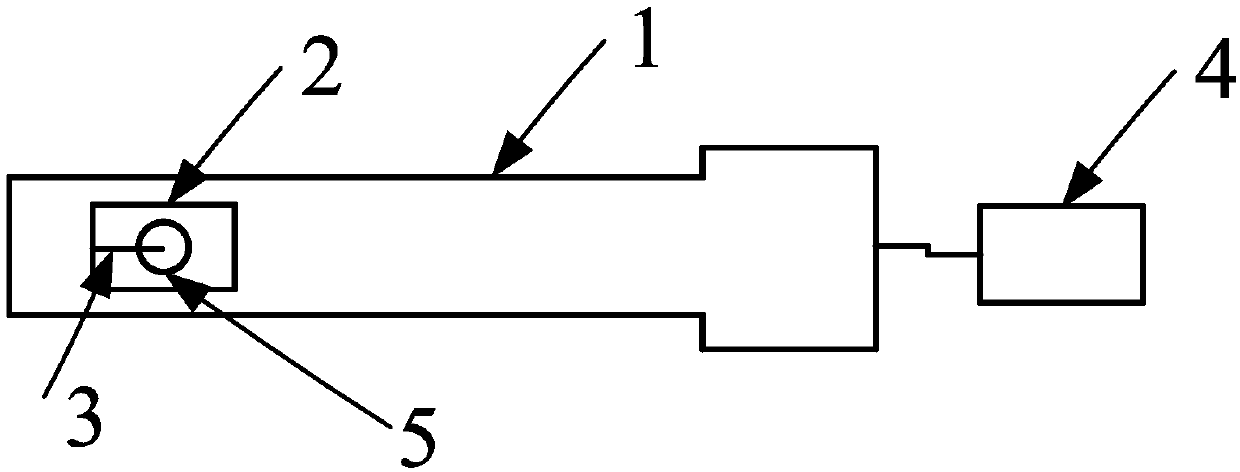
[0052] see figure 1 , the present embodiment provides a device for generating controllable vortex electron beams in TEM, the device includes: an electrical sample rod 1 , a sample chip 2 , a magnetic needle 3 wound with a conductive coil, and a magnetic field controller 4 . The end of the electrical sample rod 1 is provided with a mounting groove, and the electrode at the tail is connected to the magnetic field controller 4; the center of the sample chip 2 is provided with an aperture 5, and is placed in the mounting groove, and one end of the electrode in the sample chip 2 is connected to the sample The electrodes in the rod 2 are connected; the magnetic needle 3 wound with a conductive coil is placed horizontally on the surface of the sample chip 2, and the tip of the magnetic needle 3 wound with a conductive coil is aligned with the center of the aperture 5, and the conductive coil and the electrode sheet of the sample chip 2 are separately connected at one end.

[0053] I...

Embodiment 2

[0059] This embodiment provides a method for preparing a magnetic needle 3, specifically:

[0060] First, a magnetic wire with a diameter of 10 um and a length of 100 um is selected, and the magnetic wire is Ni.

[0061] Then, an insulating layer is deposited on the surface of the magnetic wire.

[0062] In this embodiment, the specific process of depositing an insulating layer on the surface of the magnetic wire is as follows:

[0063] (1) Measure an appropriate amount of organic solvent (the organic solvent can be cyclohexane, isopropanol) in a three-necked flask, and drop an appropriate amount of deionized water with a pipette gun, stir for about 10 minutes, and then add an appropriate amount of ammonia water , sonicate at room temperature for about 10 minutes, and let it stand; (2) mix the above-mentioned organic solvent with TEOS, and then sonicate at room temperature for about 5 minutes to form an insulating liquid; (3) put the fixed magnetic wire in a beaker, and put ...


PUM


Abstract

The invention discloses a TEM based device for generating a controllable vortex electron beam. The device is characterized by comprising an electron gun for generating a planar electron beam, a magnetic field controller, and a magnetic needle wound by a conductive coil; the magnetic needle is arranged on a planar electron beam channel via a chip controlled by electrical equipment; the magnetic field controller generates an intensity controllable magnetic field; and the magnetic field is used to modulate the phase of the planar electron beam. The invention also discloses a method for generatingthe controllable vortex electron beam via the device. The device can form magnetic field distribution similar to magnetic monopole in an electronic microscope, so that the vortex electron beam with single track angular momentum and controllable quantum number is obtained.

Description

technical field [0001] The invention belongs to the field of vortex electron beam generation, and in particular relates to a device and method for generating a controllable vortex electron beam. Background technique [0002] Predictions and experiments in recent years have proved that changing the basic structure of the electron wavefront can make the electron wave have many specific properties, which can realize new functions in common transmission electron microscopes. If the reconstructed electron beam has a continuous vortex wavefront, the electron beam is called a vortex electron beam. In a vortex electron beam, the electron probabilistic current follows a vortex path, with an azimuthal momentum component in the direction of propagation along the axis. [0003] A single vortex beam can be expressed by Ψ∝f(r)·exp(ilφ)·exp(ik z z) description, where (r, φ, z) are cylindrical coordinates; k z is the forward momentum of the beam; l is the vortex order, also known as the ...

Claims


Application Information

Patent Timeline
Patent Type & Authority Applications(China)
IPC IPC(8): H01J37/141H01J37/26
CPCH01J37/141H01J37/261H01J2237/141
Inventor 田鹤陈鑫铠孙土来杜凯任天星陈星陈琼阳
Owner ZHEJIANG UNIV
Why Eureka
Try Eureka