Supercharge Your Innovation With Domain-Expert AI Agents!

Drive Ring Offset Sensing System, Compressor and Gas Turbine

一种感测系统、燃气轮机的技术,应用在发动机功能、发动机元件、机器/发动机等方向,能够解决影响传感机构14感测精度、成本高、传感机构安装复杂等问题,达到结构简单、成本低、高发电效率的效果

Active Publication Date: 2020-01-03
SIEMENS ENERGY GLOBAL GMBH & CO KG
View PDF3 Cites 0 Cited by
  • Summary
  • Abstract
  • Description
  • Claims
  • Application Information

AI Technical Summary

Problems solved by technology

[0006] However, there are many elements in the sensing mechanism 14, each element has dimensional tolerances, and the superposition of dimensional tolerances will affect the sensing accuracy of the sensing mechanism 14
In addition, the installation of the sensing mechanism is complicated and the cost is high

Method used


Image

  • Drive Ring Offset Sensing System, Compressor and Gas Turbine
  • Drive Ring Offset Sensing System, Compressor and Gas Turbine
  • Drive Ring Offset Sensing System, Compressor and Gas Turbine

Examples


Embodiment Construction

[0051] In order to make the purpose, technical solution and advantages of the present invention clearer, the following examples are given to further describe the present invention in detail.

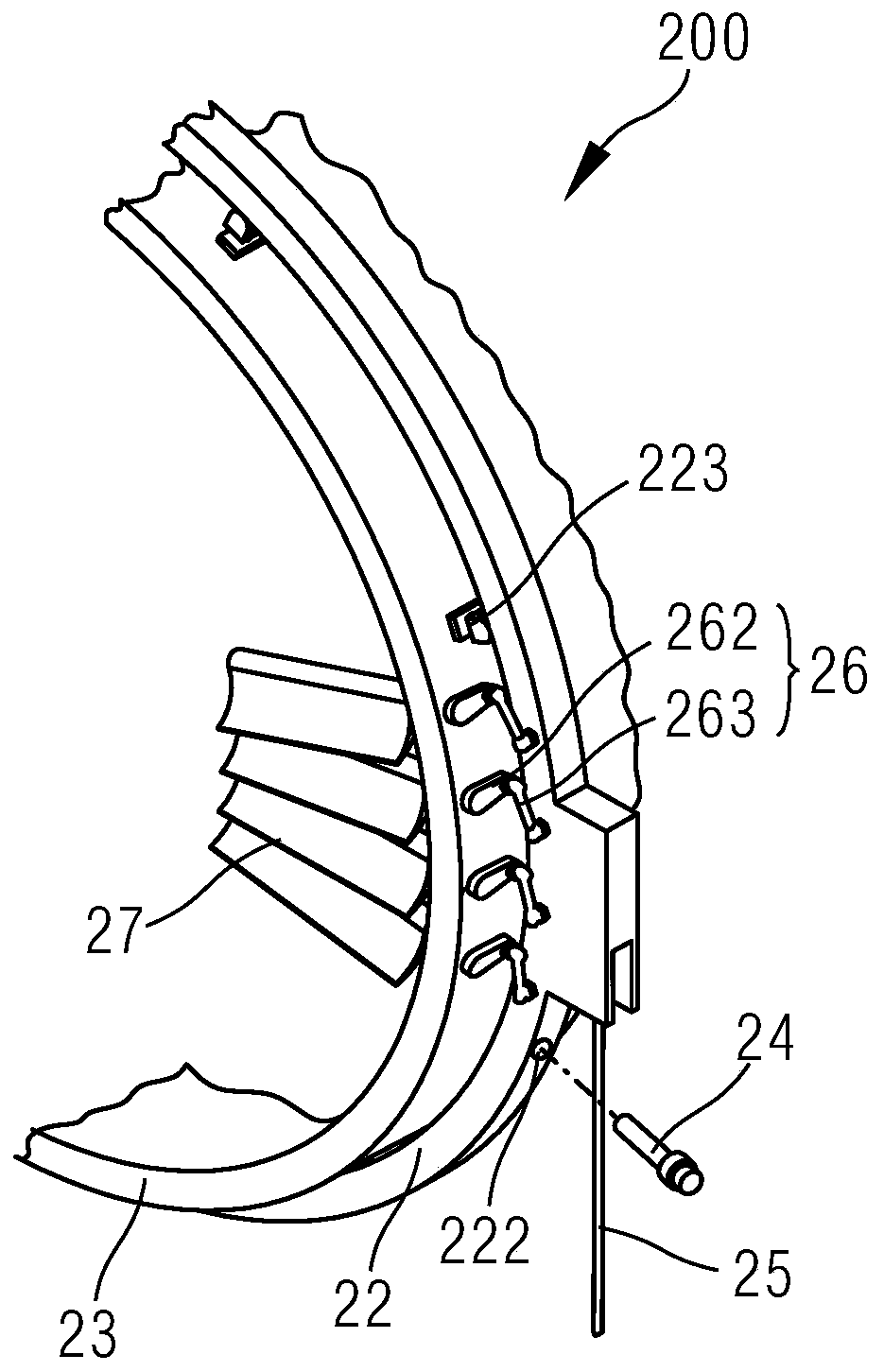
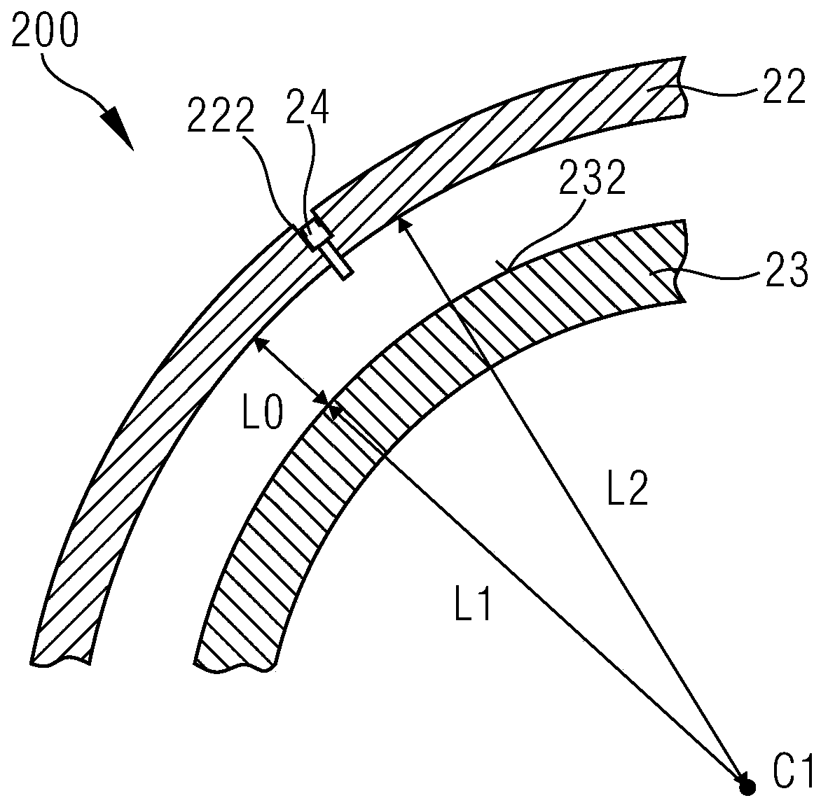
[0052] figure 2 It is a structural schematic diagram of an air compressor according to an embodiment of the present invention. image 3 for figure 2 A schematic cross-sectional view of the drive ring offset sensing system of the compressor shown. See figure 2 and image 3In this embodiment, the compressor includes a drive ring offset sensing system 200 , at least one push rod 25 , multiple linkage mechanisms 26 and multiple guide vanes 27 . The drive ring offset sensing system 200 includes at least one drive ring 22, a compressor housing 23, and at least one sensor 24. The drive ring 22 can be installed on the compressor housing 23, and is spaced apart from the compressor housing 23, namely The drive ring 22 is sheathed on the compressor housing 23 , and when the drive ring 22 is...


PUM


Abstract

The present invention provides a drive ring offset sensing system, a compressor, and a gas turbine. The drive ring offset sensing system includes: a compressor casing; at least one drive ring, and the drive ring can be Installed on the compressor housing and spaced apart from the compressor housing, the drive ring is provided with at least one installation hole, and the installation hole extends along the radial direction of the drive ring; at least one sensor, the The sensors may be arranged in the corresponding installation holes for real-time sensing of the distance between the drive ring and the compressor casing. The drive ring offset sensing system, air compressor and gas turbine of the present invention have the advantages of simple structure and low cost.

Description

technical field [0001] The invention relates to the field of energy technology, in particular to a drive ring offset sensing system, a compressor and a gas turbine. Background technique [0002] A gas turbine is a rotary power machine that uses a continuous flow of gas as a working medium to convert heat energy into mechanical work. A gas turbine generally consists of three major components: a compressor, a combustor and a turbine. When working, the compressor inhales air from the external atmosphere, and compresses it step by step through the axial flow compressor to pressurize it, and the temperature of the air increases accordingly; the compressed air is sent to the combustion chamber and mixed with the injected fuel to generate High-temperature and high-pressure gas; then the high-temperature and high-pressure gas enters the turbine part and expands to do work, pushing the turbine part to drive the compressor and the external load rotor to rotate together at high speed,...

Claims


Application Information

Patent Timeline
Patent Type & Authority Patents(China)
IPC IPC(8): F01D17/16F01D25/24
CPCF01D17/162F05D2220/3216F01D21/003F05D2220/32F05D2260/80G01B21/16
Inventor 任超孙彪游丹宁
Owner SIEMENS ENERGY GLOBAL GMBH & CO KG
Features
  • R&D
  • Intellectual Property
  • Life Sciences
  • Materials
  • Tech Scout
  • Unparalleled Data Quality
  • Higher Quality Content
  • 60% Fewer Hallucinations
Learn More