Hysteretic control for transformer based power converters

A technology of power converters and transformers, applied in high-efficiency power electronic conversion, output power conversion devices, control/regulation systems, etc., can solve problems such as converter efficiency reduction, reduce board area, reduce costs, and reduce operation The effect of temperature

Inactive Publication Date: 2018-04-17
TEXAS INSTR INC
View PDF12 Cites 1 Cited by
  • Summary
  • Abstract
  • Description
  • Claims
  • Application Information

AI Technical Summary

Problems solved by technology

For a given power level, the efficiency of the converter typically decreases as the output voltage decreases

Method used


Image

  • Hysteretic control for transformer based power converters
  • Hysteretic control for transformer based power converters
  • Hysteretic control for transformer based power converters

Examples


Embodiment Construction

[0039] Corresponding numerals and symbols in different drawings generally refer to corresponding parts, unless otherwise specified. The figures are not necessarily drawn to scale.

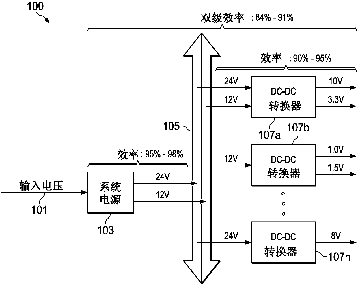
[0040] Improvements in the size and efficiency of power converters have helped reduce the size and increase efficiency of electronic products without adversely increasing device operating temperatures.

[0041] The term "coupled" may include connections with intermediate elements, and additional elements and various connections may be used between any elements described as "coupled".

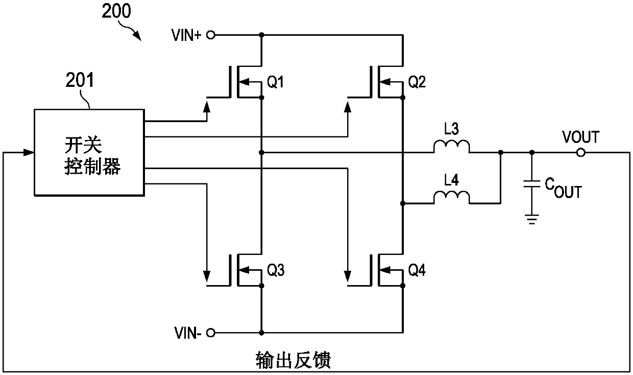
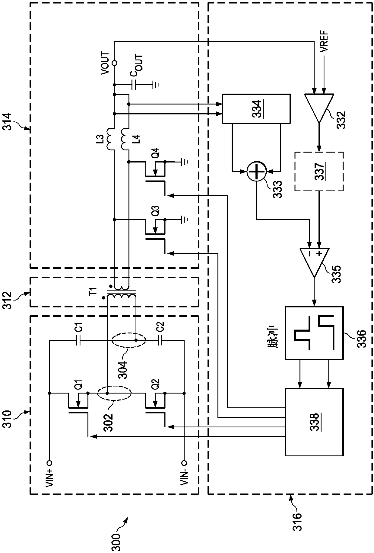
[0042] An aspect of the example embodiments provides hysteretic control of a transformer-based power converter configured to be similar in certain characteristics to a buck or step-down converter topology, however, these configurations further A transformer is used to step down the high input voltage to a low voltage while also increasing the current according to the turns ratio of the transformer. Using a transfor...


PUM


Abstract

In described examples, a converter arrangement (300) converts an input voltage (VTN) to an output voltage (VOUT). The arrangement (300) includes: a transformer (312); at least one primary side driverswitch (Q1) coupled to supply current from an input voltage terminal (VIN+) to the primary side of the transformer (312); at least one inductor (L3) coupled between the secondary side of the transformer (312) and the output voltage terminal (VOUT); at least one secondary side switch (Q3) coupled between the inductor (L3) and a ground potential; and a hysteretic controller (316) coupled to supply afirst on-time signal to the at least one primary side switch (Q1) and a second on-time signal to the at least one secondary side switch (Q3). The hysteretic controller is configured to sense the output voltage and has at least one current input coupled for sensing current flowing in the inductor (L3) and generating primary side driver switch on-time pulses to control the output voltage (VOUT).

Description

technical field [0001] The present application relates to power conversion, and more particularly to hysteretic control mechanisms for power converters. Background technique [0002] Complex electronic systems often contain a number of subassemblies on printed circuit boards (PCBs) or other modules, often located and interconnected in racks connected via back planes or connected via wiring in the shell. As the core voltages of integrated circuits have continuously dropped below 3.3 volts to 2 volts and even lower, power distribution for these subassemblies typically uses an architecture where each subassembly creates its own specific power supply using the intermediate system power supply as input. This is commonly referred to as a Distributed Power Architecture (DPA) and is a more efficient architecture for obtaining regulated power to various sub-components when compared to the Centralized Power Architecture (CPA) of traditional components. [0003] In the traditional ap...

Claims


Application Information

Patent Timeline
Patent Type & Authority Applications(China)
IPC IPC(8): H02M1/08H02M3/325H02M3/337H05K1/00
CPCH02M3/1584H02M3/33507H02M3/33546H02M3/33592H02M1/0009Y02B70/10H02M1/08
Inventor M·D·西曼
Owner TEXAS INSTR INC
Why Eureka
Try Eureka