Visible laryngoscope

A laryngoscope and lens technology, applied in the field of visual laryngoscope, can solve problems such as poor observation effect, throat tissue damage, large temperature difference, etc., and achieve the effects of easy operation and observation, less pain and less damage

Inactive Publication Date: 2018-04-20
广东名威科技有限公司
View PDF9 Cites 2 Cited by
  • Summary
  • Abstract
  • Description
  • Claims
  • Application Information

AI Technical Summary

Problems solved by technology

When the video laryngoscope is working, the video laryngoscope presses the epiglottic valley of the human oral cavity for tracheal intubation. During the intubation process, the display screen is used for observation and calibration; the laryngoscope is generally composed of a laryngoscope end and a lens. The existing The video laryngoscope has the following problems: when in use, the user holds the end of the laryngoscope and presses the lens through the patient's mouth to press the epiglottis of the oral cavity, which may cause damage to the throat tissue; the display panel is fixed on the handle of the video laryngoscope. It is inconvenient to observe the process; the temperature at the end of the laryngoscope is adjusted to a large difference from the temperature of the human body, and there will be a strong sense of comfort when using it, and the water vapor is easy to liquefy in the lens of the camera, resulting in blurring and poor observation effect

Method used


Image

  • Visible laryngoscope
  • Visible laryngoscope
  • Visible laryngoscope

Examples


Embodiment 1

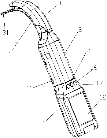
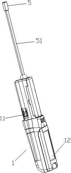
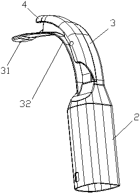
[0025] Such as figure 1 , 2 , A visual laryngoscope shown in 3 and 4, comprising a handle end 1 and a laryngoscope end; the handle end 1 is provided with a camera assembly and a display assembly; the laryngoscope end includes a connecting sleeve 2, a camera The guide channel 3 and the hydrophilic guide groove cover 4; the camera assembly includes a camera 5, and the camera 5 extends into the inner end of the camera guide channel 3 through a connecting hose 51; the hydrophilic guide groove cover 4 and the camera guide channel 3 juxtaposed with each other.

[0026] The surface of the hydrophilic guide groove cover 4 in this embodiment is coated with a nano-hydrophilic coating, which is a composite nano-coating containing many nano-components and has many nano-effects, and the nano-materials contained in it are originally The particle size is between 7 and 80nm. It can play the role of hydrophilic lubrication and prevent fogging on the surface of the laryngoscope end.

[0027...

Embodiment 2

[0034] Such as figure 1 , 2 , a video laryngoscope shown in 3, 4, 5, and 6, including a handle end 1 and a laryngoscope end; the handle end 1 is provided with a camera assembly and a display assembly; the laryngoscope end includes a connection Cover 2, camera guide channel 3 and hydrophilic guide groove cover 4; the camera assembly includes a camera 5, and the camera 5 extends into the inner end of the camera guide channel 3 through a connecting hose 51; the hydrophilic guide groove cover 4 It is juxtaposed with the camera guide channel 3.


PUM


Abstract

The invention relates to a visible laryngoscope. The visible laryngoscope comprises a handle end and a laryngoscope end; a camera assembly and a display assembly are arranged in the handle end; the laryngoscope end comprises a connecting sleeve, a camera guiding channel and a hydrophilic guiding groove sleeve; the camera assembly comprises a camera; the camera extends to an inner end of the cameraguiding channel through a connecting hose; and the hydrophilic guiding groove sleeve and the camera guiding channel are in parallel. The visible laryngoscope has hydrophilic lubricating performance.

Description

technical field [0001] The invention relates to the field of medical instruments, in particular to a video laryngoscope. Background technique [0002] The videolaryngoscope is a tool used for induction of general anesthesia, visualization of the glottis during on-site cardiac resuscitation and tracheal intubation. When the video laryngoscope is working, the video laryngoscope presses the epiglottic valley of the human oral cavity for tracheal intubation. During the intubation process, the display screen is used for observation and calibration; the laryngoscope is generally composed of a laryngoscope end and a lens. The existing The video laryngoscope has the following problems: when in use, the user holds the end of the laryngoscope and presses the lens through the patient's mouth to press the epiglottis of the oral cavity, which may cause damage to the throat tissue; the display panel is fixed on the handle of the video laryngoscope. It is inconvenient to observe the proce...

Claims


Application Information

Patent Timeline
Patent Type & Authority Applications(China)
IPC IPC(8): A61B1/267A61B1/00A61B1/04
CPCA61B1/267A61B1/00064A61B1/00131A61B1/04
Inventor 李婷
Owner 广东名威科技有限公司
Why Eureka
Try Eureka