Glass plate drilling equipment

A technology for drilling equipment and glass plates, which is applied to stone processing equipment, stone processing tools, work accessories, etc., and can solve the problems of heavy labor, laborious work, and low productivity

Pending Publication Date: 2018-04-20
威海市银河光电设备股份有限公司
View PDF6 Cites 1 Cited by
  • Summary
  • Abstract
  • Description
  • Claims
  • Application Information

AI Technical Summary

Problems solved by technology

[0003] The present invention aims at the low efficiency of manual handling, heavy labor, and low hole positioning accuracy during drilling and installation of the existing glass plate drilling equipment, and frequent adjustment or replacement of positioning blocks is required when processing different holes, which is time-consuming, laborious, and low in productivity. To solve the technical problem, it is necessary to provide a method of electric spindle drilling for glass plates that does not require manual handling, and is grasped and conveyed by a manipulator, which improves the conveying efficiency, reduces labor intensity, and is conducive to the improvement of hole positioning accuracy. Different holes When processing, there is no need to adjust or replace the positioning block, and the positioning parts of the equipment can be used in common, which saves positioning time, reduces labor intensity, and improves the production efficiency of the glass plate drilling equipment

Method used


Image

  • Glass plate drilling equipment
  • Glass plate drilling equipment
  • Glass plate drilling equipment

Examples


Embodiment Construction

[0033] The present invention will be further described below in conjunction with the examples.

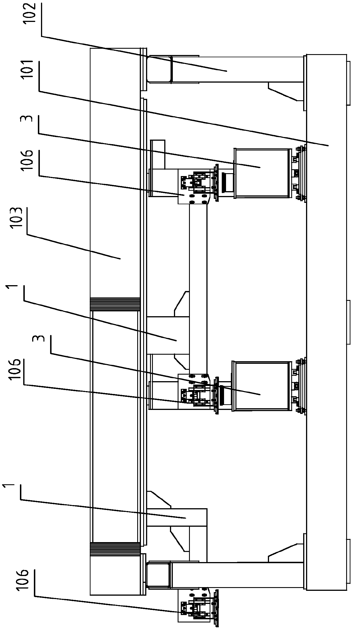
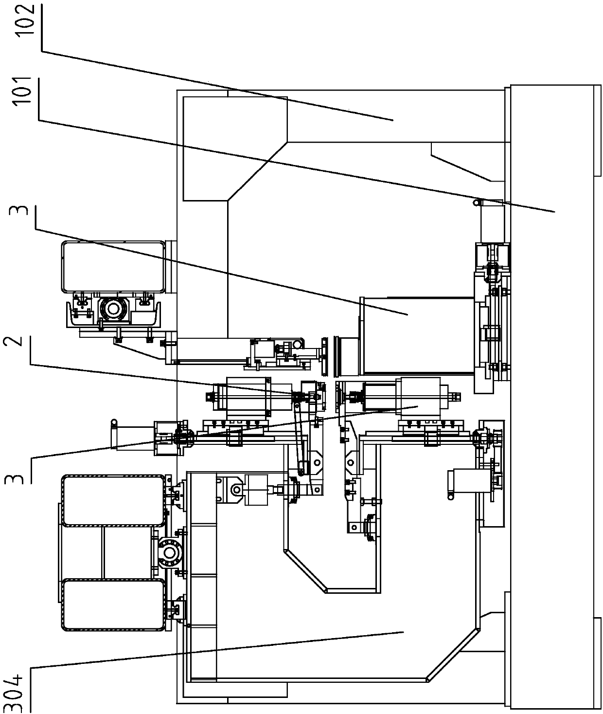
[0034] The first part is the conveying part 1 that quickly transports the glass plate to the designated station, the second part is the clamping part 2 that clamps the glass plate and stabilizes it, and the third part is through the rotating platform, X-axis movement and Y-axis movement A positioning component 3 for accurately positioning the drilling position of the glass plate.

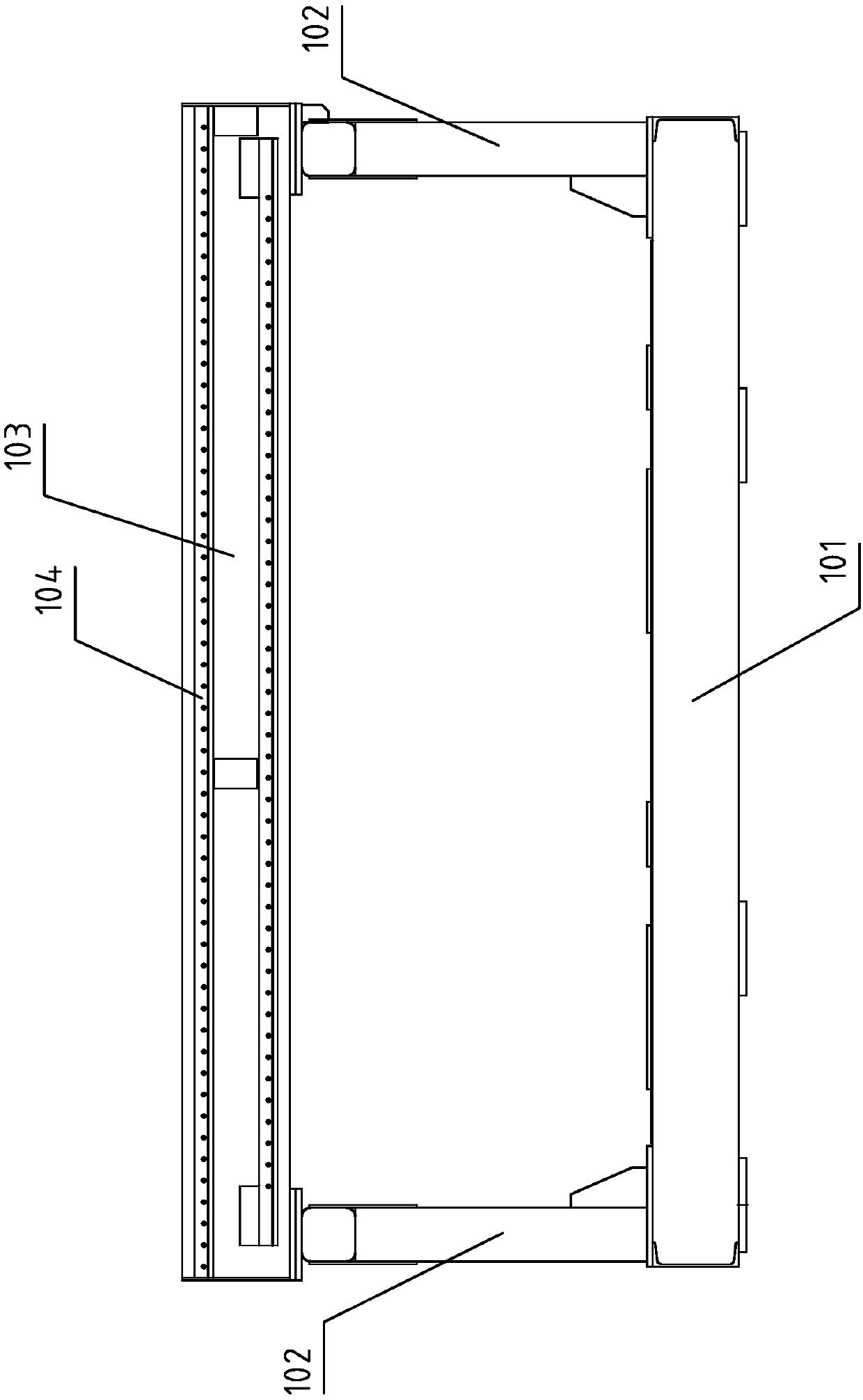
[0035] The conveying part 1 is provided with a body base 101, and the left and right sides of the body base 101 are provided with a column assembly 102, and a Y-axis conveying beam 103 is erected on the column assembly 102, and two sets of upper and lower Y-axis rails 104 are arranged on the Y-axis conveying beam 103. The axis rail 104 is provided with a slider assembly 105 that can slide along the Y axis rail 104. The slider assembly is provided with a slider 1051. The slider 1051 is provided with a sli...


PUM


Abstract

The invention provides glass plate drilling equipment. The glass plate drilling equipment solves the technical problems that during glass plate drilling and mounting, the manual carrying efficiency islow, the labor amount is large, the positioning precision of holes is low, during machining of the different holes, a positioning block is required to be adjusted or replaced frequently, both time and labor are consumed, and the productivity is low. The glass plate drilling equipment is provided with a conveying part, a clamping part and a positioning part, wherein the conveying part is providedwith a machine body base, a sliding block assembly, a manipulator assembly and a glass sucking disc; and the clamping part is provided with a clamping bow-shaped frame, air cylinder brackets are arranged on the upper portion and the lower portion of the clamping bow-shaped frame, the air cylinder brackets are provided with clamping air cylinders, a clamping bow-shaped frame body and glass chucks,and the positioning part is provided with an X axis rail, a positioning sliding block, a positioning servo motor, an electric main shaft, a tubular glass cutter and a bow-shaped frame servo motor. Theglass plate drilling equipment can be widely used in the glass plate drilling and mounting process.

Description

technical field [0001] The invention relates to a glass plate processing equipment, in particular to a glass plate drilling equipment. Background technique [0002] The front windshield, rear windshield, side window glass and various glass plates used in social life are commonly used in people's daily social activities. The production of these glass products is to use A variety of glass plate processing equipment processes glass plate blanks through multiple processes. Glass plate processing includes glass plate cutting, glass plate edging, glass plate drilling and other processes. The current common operation method for glass plate drilling is to calculate the hole to two positions according to the position of the hole on the glass plate drilling equipment. The distance between the positioning sides, two positioning blocks are pre-fixed, and the glass plate is manually moved to the glass plate tray during production. The glass plate tray is pre-installed with a universal b...

Claims


Application Information

Patent Timeline
IPC IPC(8): B28D1/14B28D7/00B28D7/04B28D7/02
CPCB28D1/14B28D7/00B28D7/005B28D7/02B28D7/04B28D7/046
Inventor 张昭松邹积强王义忠
Owner 威海市银河光电设备股份有限公司
Why Eureka
Try Eureka