
Pantograph and electric vehicle with same

A technology for electric vehicles and pantographs, applied in electric vehicles, current collectors, vehicle components, etc., can solve the problems of affecting charging safety and reliability, high maintenance costs, derailment of power supply lines, etc., and is conducive to automatic access. and separation, improve safety and reliability, and achieve the effect of high-voltage safe power consumption

Pending Publication Date: 2018-04-20
东北大学秦皇岛分校
View PDF0 Cites 15 Cited by
  • Summary
  • Abstract
  • Description
  • Claims
  • Application Information

AI Technical Summary

Problems solved by technology

However, the pantograph of the existing structure maintains the pressure by squeezing the power supply network upwards, and the structure is complex and the maintenance cost is high
When docking and charging between the pantograph slide and the power supply line, the pantograph slide cannot adjust its height adaptively to make it in stable contact with the power supply line, which will seriously affect the safety and reliability of charging, and may be damaged in severe cases vehicle
At the same time, the existing pantograph structure makes it easy for the vehicle to derail from the power supply line when it deviates left and right in the lane. Once derailed, it needs to be parked and manually reset. This power supply method cannot meet the driving needs of electric vehicles, especially those driving on expressways. Require

Method used


Image

  • Pantograph and electric vehicle with same
  • Pantograph and electric vehicle with same
  • Pantograph and electric vehicle with same

Examples


Embodiment 1

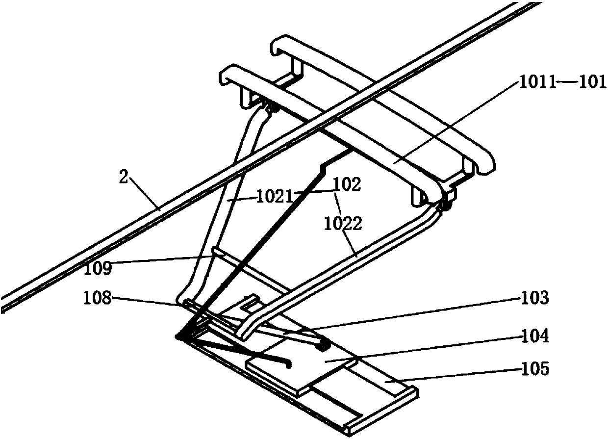
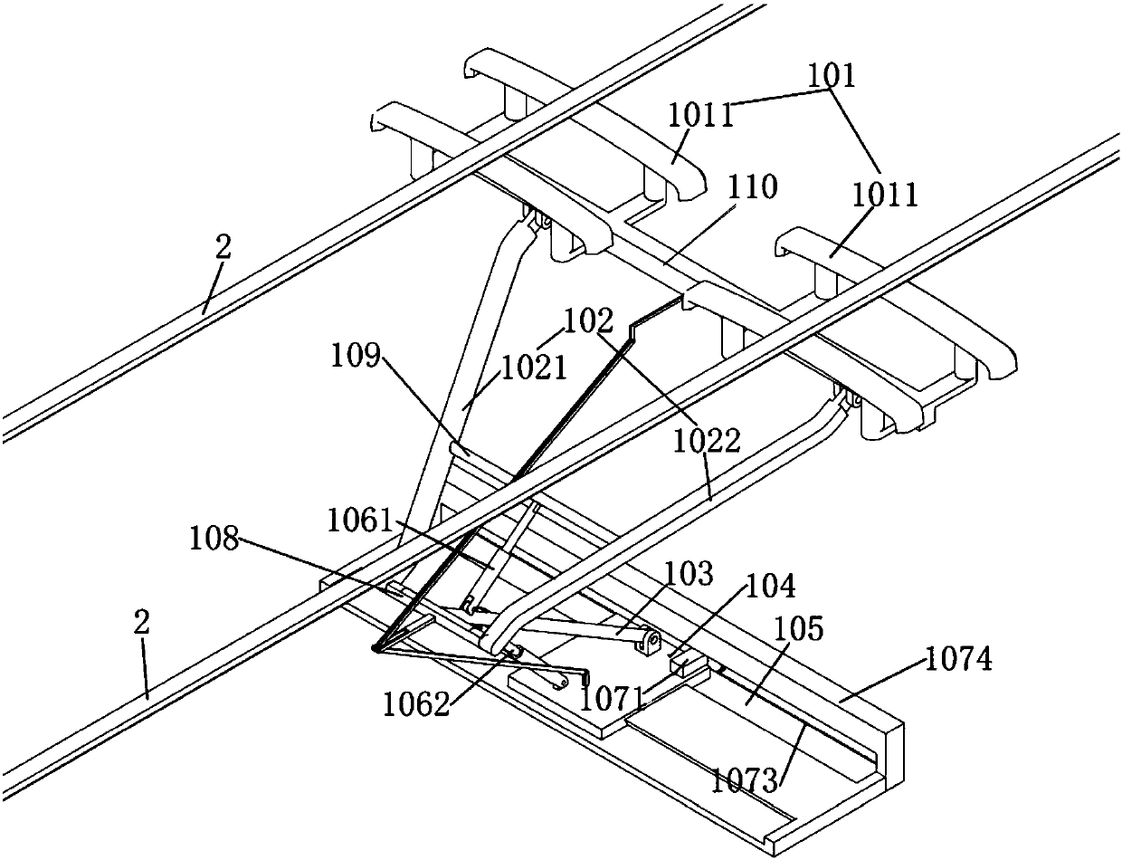
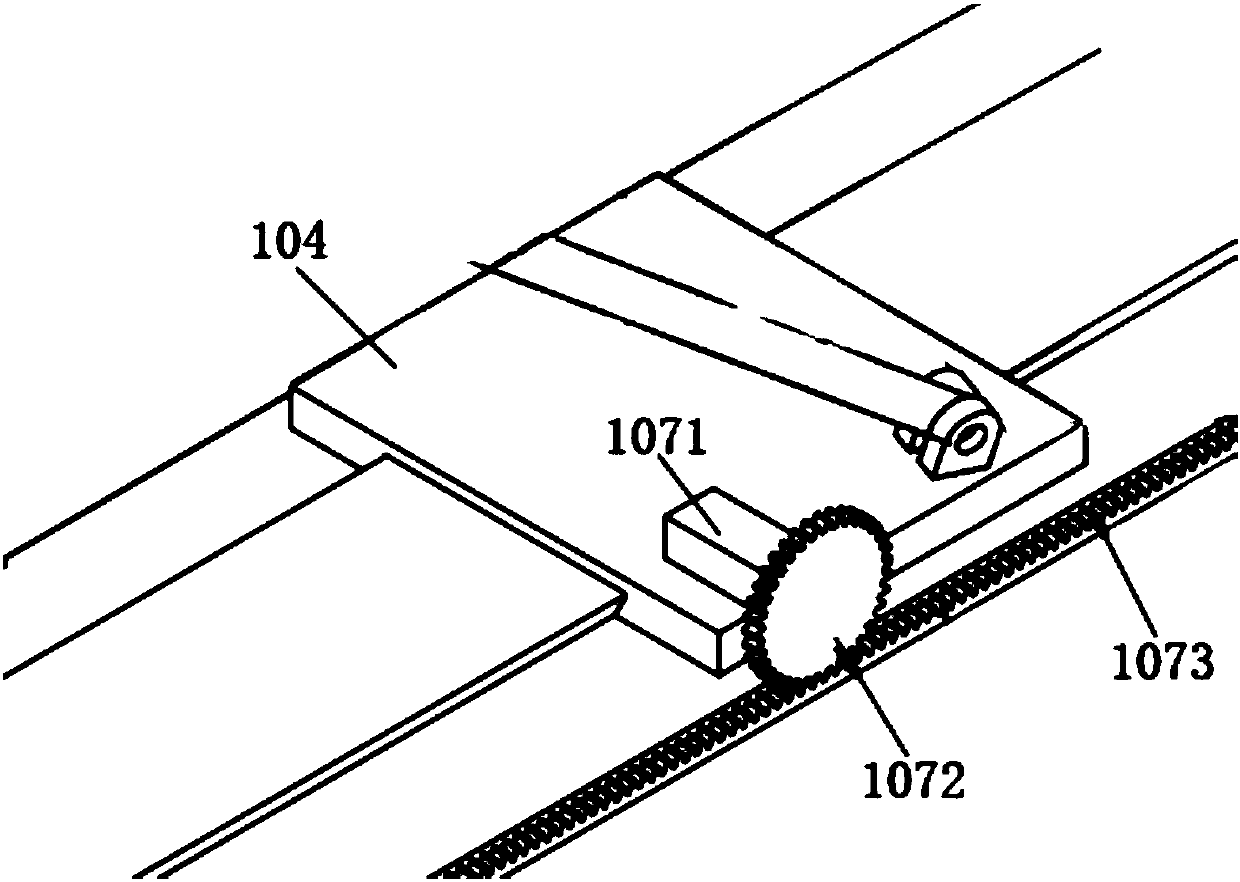
[0036] Embodiment 1 of the present invention: a pantograph includes a pantograph assembly 1, such as figure 1 As shown, the pantograph assembly 1 includes a pantograph slide assembly 101 perpendicular to the power supply line 2, the pantograph slide assembly 101 obtains electric power by contacting the power supply line 2, and the pantograph assembly 1 also It includes an upper support arm 102 , a lower support arm 103 , a pantograph support 104 , a moving track 105 , a telescoping mechanism 106 and a translation mechanism 107 . The moving track 105 is provided with a movable pantograph support 104, one end of the lower support arm 103 is installed on the pantograph support 104, and the other end of the lower support arm 103 is connected with an upper The end of the support arm 102 , and the other end of the upper support arm 102 is installed with a pantograph slide assembly 101 . The moving track 105 is also provided with a translation mechanism 107, which can realize the le...

Embodiment 2

[0041] Embodiment 2: as figure 1 and figure 2 As shown, a pantograph includes a pantograph assembly 1, the pantograph assembly 1 includes a pantograph slide assembly 101 perpendicular to the power supply line 2, and the pantograph slide assembly 101 contacts the power supply line 2 To obtain electric power, the pantograph assembly 1 further includes an upper support arm 102 , a lower support arm 103 , a pantograph support 104 , a moving track 105 , a telescopic mechanism 106 and a translation mechanism 107 . The moving track 105 is provided with a movable pantograph support 104, one end of the lower support arm 103 is installed on the pantograph support 104, and the other end of the lower support arm 103 is connected with an upper The end of the support arm 102 , and the other end of the upper support arm 102 is installed with a pantograph slide assembly 101 . The moving track 105 is also provided with a translation mechanism 107, which can realize the left and right moveme...

Embodiment 3

[0043] Embodiment 3: An electric vehicle, a fixed base 3 is installed on the top of the electric vehicle, and a pantograph is arranged on the upper part of the fixed base 3 , and the pantograph obtains electric energy from a power supply line 2 . Such as Figure 5 and Figure 7 As shown, the electric vehicle also includes a data processing unit 4 and a tracking device 5, and the tracking device 5 is placed on the top of the electric vehicle, and the telescopic mechanism 106, the translation mechanism 107 and the tracking device 5 are all signal-connected to Data processing unit 4. After the tracking device 5 intelligently recognizes the special logo and shape of the power supply line 2 by way of grayscale recognition, it transmits this signal to the data processing unit 4, and the data processing unit 4 can issue a control signal according to the power demand of the electric vehicle. Commands are given to the telescopic mechanism 106 and the translation mechanism 107, and th...


PUM


Abstract

The invention relates to the field of power supply technologies for electric vehicles, in particular to a pantograph and an electric vehicle with the same. The pantograph comprises a pantograph assembly. The pantograph assembly comprises a pantograph slide plate assembly, an upper support arm, a lower support arm, a pantograph support, movable tracks, expansion mechanisms and a translation mechanism, the pantograph slide plate assembly is perpendicular to a power supply line, the translation mechanism is further arranged on the movable tracks, and the expansion mechanisms are arranged betweenthe upper support arm and the pantograph support and between the lower support arm and the pantograph support. The pantograph is arranged on the top of the electric vehicle. The electric vehicle further comprises a data processing unit and a tracking device. The tracking device is arranged on the top of the electric vehicle, and the expansion mechanisms, the translation mechanism and the trackingdevice are in signal connection with the data processing unit. The pantograph and the electric vehicle have the advantages that the height of the pantograph can be adaptively adjusted, the pantographcan be in excellent contact with the power supply line even when the electric vehicle is deviated in lanes in the left-right directions, accordingly, power supply can be guaranteed against being interrupted, and the charge safety of the electric vehicle can be improved.

Description

technical field [0001] The invention relates to the technical field of electric vehicle power supply, in particular to a pantograph and an electric vehicle using the pantograph. Background technique [0002] The pantograph is an electrical device for an electric vehicle to obtain electric energy from the power supply network. It is installed on the roof of the electric vehicle. In the charging system, the pantograph is an essential component. However, the pantograph of the existing structure maintains the pressure by pressing the power supply network upwards, and the structure is complex and the maintenance cost is high. When docking and charging between the pantograph slide and the power supply line, the pantograph slide cannot adjust its height adaptively to make it in stable contact with the power supply line, which will seriously affect the safety and reliability of charging, and may be damaged in severe cases vehicle. At the same time, the existing pantograph structur...

Claims


Application Information

Patent Timeline
Patent Type & Authority Applications(China)
IPC IPC(8): B60L5/22B60L5/28
CPCB60L5/22B60L5/28
Inventor 郭献章张娟霞魏永涛郑晓涛李嘉鹏常博浩高君彬胡文博陶帅帅杨国茗周佳洋武帅李玹雨孙鑫鹏
Owner 东北大学秦皇岛分校
Learn More