
Prefabricated frame adopting combination of steel reinforced concrete columns and steel beams

A concrete column, prefabricated assembly technology, applied in construction, building construction and other directions, can solve the problems of inconvenient prefabrication, transportation, hoisting and assembly, and difficulty in achieving "equivalent cast-in-place, large internal force at beam-column joints, etc." Intermittent, reduced transportation and hoisting costs, and the effect of strong energy consumption

Pending Publication Date: 2018-04-20
CHONGQING UNIV
View PDF0 Cites 14 Cited by
  • Summary
  • Abstract
  • Description
  • Claims
  • Application Information

AI Technical Summary

Problems solved by technology

[0004] ①Reinforced concrete has low strength, large cross-section and heavy weight, which brings a lot of inconvenience to prefabrication, transportation, hoisting and assembly;
[0005] ②The internal force at the beam-column joint is relatively large, the stress situation is complicated, there are many steel bars in the joint area, the construction of on-site steel bar binding and concrete pouring is difficult, the construction quality is unstable, and it is difficult to achieve the effect of "equivalent to cast-in-place", so on-site assembly is carried out here , it is difficult to meet the basic requirements of the seismic conceptual design of "strong nodes, weak components";
[0006] ③Using the integral post-casting assembly method, it is necessary to wait for the concrete poured on site to reach a certain strength before proceeding to the construction of the next process. The technical interval is long, which affects the construction period

Method used


Image

  • Prefabricated frame adopting combination of steel reinforced concrete columns and steel beams
  • Prefabricated frame adopting combination of steel reinforced concrete columns and steel beams
  • Prefabricated frame adopting combination of steel reinforced concrete columns and steel beams

Examples


Embodiment Construction

[0049] The present invention will be further described below in conjunction with the examples, but it should not be understood that the scope of the subject of the present invention is limited to the following examples. Without departing from the above-mentioned technical idea of ​​the present invention, various replacements and changes made according to common technical knowledge and conventional means in this field shall be included in the protection scope of the present invention.

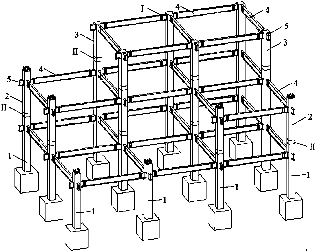
[0050] A prefabricated assembled frame adopting a combination of steel concrete columns and steel beams, including a prefabricated assembled frame formed by combining several steel concrete columns and steel beams 4.

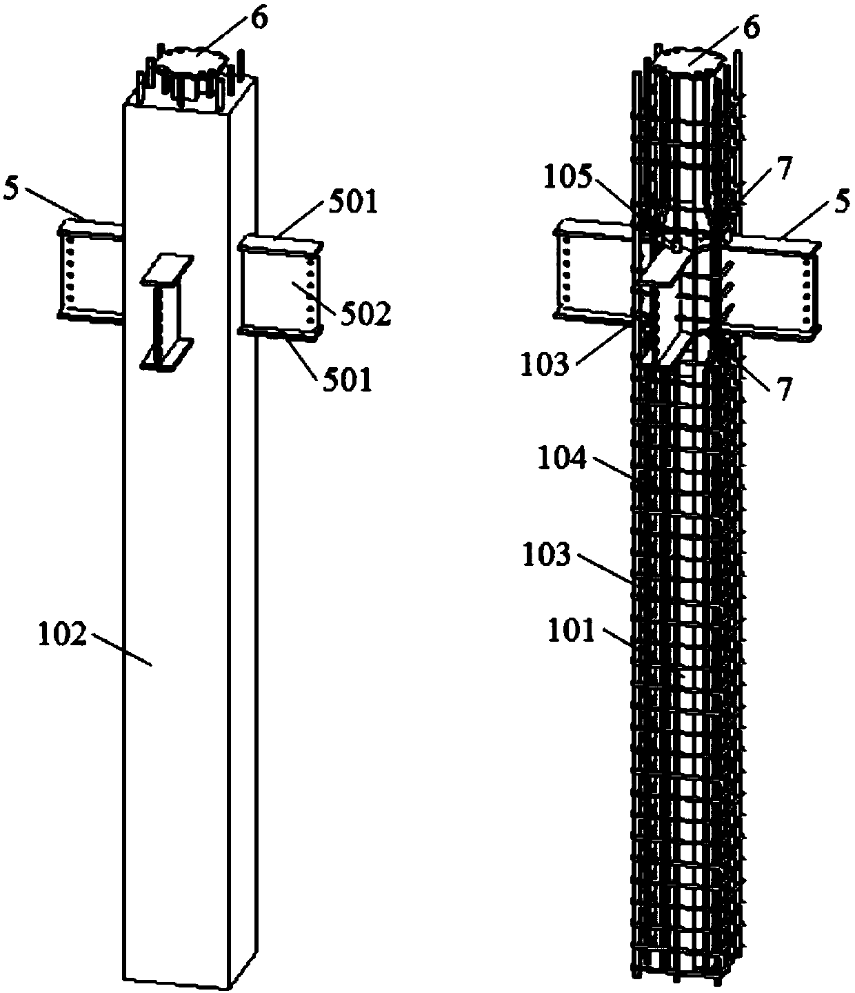
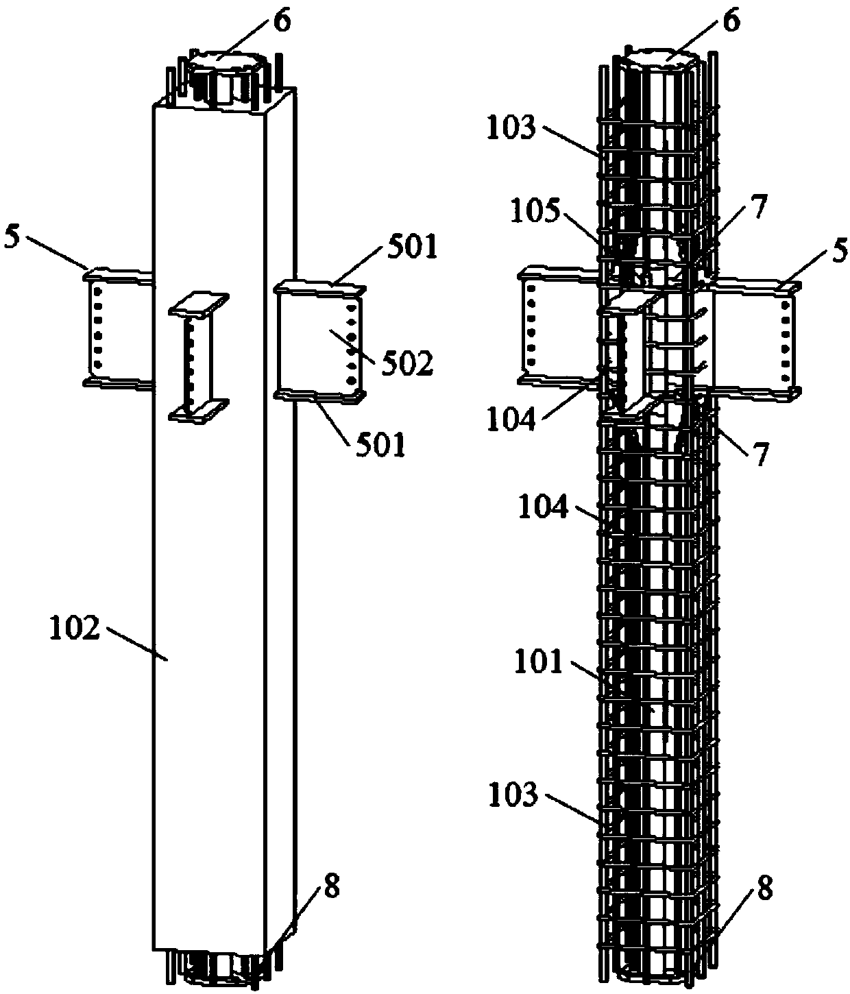
[0051] The steel concrete column includes a cross-shaped steel column 101 , concrete 102 , longitudinal steel bars 103 inside the column, stirrups 104 and connecting short sleeves 105 .

[0052] The cross-shaped steel column 101 is configured with 2 to 4 steel corbels 5 (4 central...


PUM


Abstract

The invention provides a prefabricated frame adopting combination of steel reinforced concrete columns and steel beams. The prefabricated frame comprises a plurality of bottom layer column units, a plurality of middle layer column units, a plurality of top layer column units and a plurality of cross beams, and the bottom layer column units, the middle layer column units, the top layer column unitsand the cross beams are all preformed components. The upper ends of the bottom layer column units are provided with upper column connectors, and the upper ends and the lower ends of the middle layercolumn units are provided with upper column connectors and lower column connectors correspondingly. The middles of the middle layer column units are provided with beam-column connecting joints. The lower ends of the top layer column units are provided with lower column connectors, and the upper ends of the top layer column units are provided with column-column connecting joints. The two ends of the cross beams are provided with beam connectors. The components are assembled on site, the complex technological process of traditional construction in a joint area is avoided, the column connectors and the beam connectors only need to be assembled outside the joint area, and thus the construction efficiency and the engineering quality are greatly improved.

Description

technical field [0001] The invention relates to the technical field of construction engineering, in particular to a prefabricated assembly frame that adopts a combination of steel concrete columns and steel beams. Background technique [0002] The prefabricated structure decomposes the structure into a number of independent component units (such as beams, columns, walls, panels, etc.), each unit is preset in the factory, and connected by a special connection method on site to form a whole. The prefabricated structure has the characteristics of energy saving, environmental protection, fast construction speed and high construction precision. At present, research on the form of prefabricated structures and on-site connection methods has become the most dynamic direction. [0003] Prefabricated frame is one of the most commonly used forms of prefabricated structures. Traditional prefabricated frames mostly use reinforced concrete beams and columns, and the joints of beams and c...

Claims


Application Information

Patent Timeline
IPC IPC(8): E04B1/18E04B1/19E04B1/30E04B1/24
CPCE04B1/185E04B1/19E04B1/24E04B1/30
Inventor 王志军熊刚傅剑平杨波周淑容
Owner CHONGQING UNIV
Learn More