Coronary plug mounting tool

A technology for installing tools and crowns, which is applied in the direction of wellbore/well components, earthwork drilling and production, etc., to achieve the effect of simple and reliable operation, ensuring reliability and simple structure

Inactive Publication Date: 2018-04-20
CHONGQING QIANWEI SCI & TECH GRP
View PDF5 Cites 0 Cited by
  • Summary
  • Abstract
  • Description
  • Claims
  • Application Information

AI Technical Summary

Problems solved by technology

Restricted by foreign technical blockades and other reasons, there are few domestic institutions that conduct research on crown plug installation tools, and there are also few manufacturers that can manufacture deep-water Christmas tree crown plug installation tools.

Method used


Image

  • Coronary plug mounting tool
  • Coronary plug mounting tool
  • Coronary plug mounting tool

Examples


Embodiment 1

[0059] Embodiment one, such as Figure 1 to Figure 4 Shown:

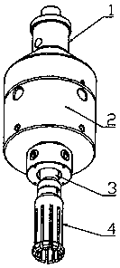
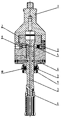
[0060] A crown plug installation tool, including a body 2, an upper joint 1, a mandrel 3, a pressure spring, a lock block 7 and a lock block limiter;

[0061] The body 2 is a cylindrical structure as a whole, and a stepped hole is provided through the interior of the body 2 along the axial direction; the body 2 is top, middle and bottom from top to bottom, wherein the top and the upper joint 1 Detachable fixed connection; the outer diameter of the middle part is greater than the inner diameter of the drive cylinder of the crown plug and is used to push the upper end surface of the drive cylinder of the crown plug; the outer diameter of the bottom is smaller than the outer diameter of the middle part and can be inserted into the drive cylinder of the crown plug Inside, and the outer surface of the bottom is radially provided with lock block installation holes, the lock block installation holes are at least two evenl...

Embodiment 2

[0092] Embodiment two, not shown in the figure:

[0093] The difference between this embodiment and the foregoing embodiment is that:

[0094] There is a block at the outer end of the mounting hole of the lock block, and there is a hole in the middle of the block;

[0095] The locking block is a bar-shaped structure in which the outer surface is slidingly fitted with the inner surface of the piercing hole;

[0096]The stopper of the lock block is a piston rod, and the end face of the piston rod is vertically fixedly connected with the end of the lock block away from the hole, and the side of the piston rod and the inner surface of the lock block installation hole are slidingly fitted. connected;

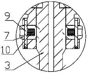
[0097] The compression spring is sleeved on the locking block and its two ends abut between the baffle plate and the locking block limiter.

[0098] This embodiment also enables the outer end of the lock block to extend or retract under the drive of the mandrel 3 . However, this ...


PUM


Abstract

The invention discloses a crown plug installation tool, which is characterized in that: it includes a body, an upper joint, a mandrel, a compression spring, a lock block and a lock block limiter; a stepped hole is arranged axially through the inside of the body; the body From top to bottom, there are top, middle and bottom, wherein, the top and the upper joint are detachably fixedly connected; the outer surface of the bottom is provided with locking block mounting holes radially, and each locking block mounting hole is equipped with a compression spring , lock block and lock block limiter, the lock block can extend or retract the lock block installation hole; the outer surface of the upper section of the mandrel and the inner surface of the step hole are connected by sliding fit, and the upper end of the mandrel is the limit end ; When the limit end abuts against the step surface of the step hole, the part of the lower end of the mandrel exposed outside the bottom of the body is the unlocking section, and the diameter of the outer surface of the unlocking section gradually decreases from top to bottom and is used for the complete shrinkage of the lock block Return to the lock block mounting hole. The crown plug installation tool of the present invention has the advantages of reliable connection, simple and convenient manipulation.

Description

technical field [0001] The invention belongs to the field of installation tools for oil and gas drilling equipment, and in particular relates to a crown plug installation tool. Background technique [0002] Subsea tree is an extremely important system in offshore oil exploitation, and its structure is very complex. [0003] Existing subsea trees are generally divided into vertical trees and horizontal trees. Among them, the main key components of horizontal trees include tubing hangers, crown plugs, inner tree caps, connectors, SCM, etc. . Two crown plugs are arranged vertically in the horizontal tree, wherein the lower crown plug is installed in the tubing hanger, and the upper crown plug is installed in the tubing hanger or the inner tree cap. The crown plug is used to block the upward flow or overflow of crude oil, so that the crude oil flows out from the production channel hole on the side of the tubing hanger, and reaches the production manifold through the valve grou...

Claims


Application Information

Patent Timeline
Patent Type & Authority Applications(China)
IPC IPC(8): E21B23/00
CPCE21B23/00
Inventor 李荣叶天源林彩明谭双妮龚光辉石静
Owner CHONGQING QIANWEI SCI & TECH GRP
Why Eureka
Try Eureka