Coal mine gas extraction hole plugging device

A plugging device and coal mine gas technology, which is applied in the direction of gas discharge, safety devices, mining equipment, etc., can solve problems such as threats to the life safety of operators, damage to the underground working environment, and easy foaming of polyurethane to achieve good plugging effect, Simple structure, good sealing effect

Active Publication Date: 2018-04-20
CCTEG SHENYANG RES INST
View PDF6 Cites 3 Cited by
  • Summary
  • Abstract
  • Description
  • Claims
  • Application Information

AI Technical Summary

Problems solved by technology

[0002] At present, in the field of coal mines, it is often necessary to drill into coal seams and gas accumulation areas for coal mine gas drainage to prevent safety accidents such as gas explosions and gas outbursts. Gas leakage will cause damage to the underground operating environment and threaten the safety of operators. The traditional method of sealing drainage holes is to use polyurethane or cement slurry for sealing. Polyurethane is easy to foam. There is a problem of leakage. When the cement slurry is used to seal the hole, gas leaks out continuously during the process of pouring the cement slurry into the hole. Before the cement slurry dries and hardens, the gas gas will open a certain gap in the filled cement slurry, causing The plugging effect of gas leakage is not good. The existing mechanical plugging device, after the plugging is completed, with the passage of time, the gas accumulation in the hole becomes larger and the pressure increases, and the fixed plugging device is pushed by pressure. Slowly appear loose, appear air leakage, use effect is not good

Method used


Image

  • Coal mine gas extraction hole plugging device

Examples


Embodiment Construction

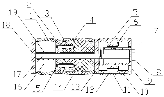
[0025] A coal mine gas drainage hole sealing device of the present invention is realized in this way. When using, when sealing the coal mine gas drainage hole, firstly insert the elastic sleeve (1) into the coal mine gas drainage hole, and then use The hex wrench rotates the rotating block (7), the rotating block (7) drives the sliding cylinder (6) to rotate, the sliding cylinder (6) drives the main cylinder (10) to rotate through the guide sleeve (9), and then the main cylinder (10) is screwed into In the coal mine gas drainage hole, at this time, the main cylinder (10) seals the coal mine gas drainage hole. As time goes by, the gas concentration in the hole increases continuously, and the gas in the hole enters the two holes on the main cylinder (10). air guide slots (12), and then flow into the main cylinder (10) through the air inlet holes on the corresponding cover plate (5), and then enter the sliding cylinder (6) through multiple through holes on the sliding cylinder (6)...


PUM


Abstract

The invention discloses a coal mine gas extraction hole plugging device. According to the coal mine gas extraction hole plugging device, after an extraction hole is plugged, along with continuous increasing of the gas amount in the hole, the hole is plugged secondarily through mixing of water and cement. The coal mine gas extraction hole plugging device is characterized in that two connecting plates are placed at the two ends of an elastic sleeve correspondingly and are made of rigid materials; a through hole is formed in the middle of the connecting plate at one end of the elastic sleeve, andone end of a main body cylinder is placed on the connecting plate at one end of the elastic sleeve; a fastening thread is arranged on the outer side of the main body cylinder; the main body cylinderis made of a rigid material, and two gas guiding grooves are symmetrically formed in the main body cylinder and communicate with the interior of the main body cylinder; two cover plates are placed onthe inner walls of the main body cylinder correspondingly and correspond to the two gas guiding grooves; a plurality of gas inlet holes are formed in the cover plates, and the diameters of the gas inlet holes are increased gradually from an inlet to an outlet; and a partition plate is placed on the elastic sleeve and partitions the interior of the elastic sleeve into a water storage cavity and a cement cavity.

Description

technical field [0001] The invention relates to a coal mine gas drainage hole sealing device, which relates to a device for sealing the drainage holes during the coal mine gas drainage, and belongs to the field of mining equipment. In particular, it relates to a device for secondarily sealing the holes by mixing water and cement as the amount of gas in the holes increases after the holes are blocked. Background technique [0002] At present, in the field of coal mines, it is often necessary to drill into coal seams and gas accumulation areas for coal mine gas drainage to prevent safety accidents such as gas explosions and gas outbursts. Gas leakage will cause damage to the underground operating environment and threaten the safety of operators. The traditional method of sealing drainage holes is to use polyurethane or cement slurry for sealing. Polyurethane is easy to foam. There is a problem of leakage. When the cement slurry is used to seal the hole, gas leaks out continuo...

Claims


Application Information

Patent Timeline
IPC IPC(8): E21B33/03E21F7/00
CPCE21B33/03E21F7/00
Inventor 不公告发明人
Owner CCTEG SHENYANG RES INST
Why Eureka
Try Eureka