AI technical title is built by PatSnap AI team. It summarizes the technical point description of the patent document.
A technology for automobile exhaust and purifiers, which is applied in exhaust devices, machines/engines, and air quality improvement, etc., can solve the problems of gas easily scalding pedestrians, carbon particles easily adhering to the device, low activity of purifiers and difficult to purify, etc. , to achieve the effect of improving safety and prolonging service life
Inactive Publication Date: 2018-04-20
宁波市河清源技术转移服务有限公司
View PDF0 Cites 3 Cited by
Summary
Abstract
Description
Claims
Application Information
AI Technical Summary
This helps you quickly interpret patents by identifying the three key elements:
Problems solved by technology
Method used
Benefits of technology
Problems solved by technology
[0004] The purpose of the present invention is to provide a kind of automobile exhaust gas purifier, to solve the problem that carbon particles are easy to adhere to the device proposed in the above background technology, the purifier has low activity and is difficult to purify when the car is started, and the discharged gas is easy to burn pedestrians.
Method used
Image
Click on the blue label to locate the original text in one second.
Reading with bidirectional positioning of images and text.
Examples
Embodiment 1
[0027] A method for preparing an exhaust gas catalyst, the method comprising the following steps:
[0028] Step 1, 5molMg(NO 3 ) 2 Add it into 500m1 deionized water, heat and stir at 80°C to make a magnesiumnitrate solution, and then
[0029] After adding 18mo1Zn-MOF@Al 2 o 3 , after fully adsorbed, will be loaded with Mg 2+ Zn-MOF@Al 2 o 3 Place in a vacuum drying oven, heat up to 105°C at a rate of 5°C / min, and then dry at a constant temperature for 12 hours;
[0030] Step 2. Take out the dry matter and crush it into 200-mesh particles, put it into the muffle furnace and raise the temperature to 120°C at 3°C / min, keep the temperature for 30min, then raise the temperature to 350°C at 3 / min, hold the temperature for 120min, and then set the temperature at 5°C / min Raise the temperature to 450°C, keep the temperature constant for 4 hours, and take out the material after natural cooling;
[0031] Step 3, 0.5molTiCl 4 Add to 300m1 water, pH=10, fully hydrolyzed to produc...
Embodiment 2
[0038] Step 1, 3molMg(NO 3 ) 2 Add it into 500m1 deionized water, heat and stir at 80°C to make a magnesiumnitrate solution, and then
[0039] After adding 18mo1Zn-MOF@Al 2 o 3 , after fully adsorbed, will be loaded with Mg 2+ Zn-MOF@Al 2 o 3 Place in a vacuum drying oven, heat up to 105°C at a rate of 5°C / min, and then dry at a constant temperature for 12 hours;
[0040] All the other steps are the same as in Example 1.
Embodiment 3
[0042] Step 1, 1molMg(NO 3 ) 2 Add it into 500m1 deionized water, heat and stir at 80°C to make a magnesiumnitrate solution, and then
[0043] After adding 18mo1Zn-MOF@Al 2 o 3 , after fully adsorbed, will be loaded with Mg 2+ Zn-MOF@Al 2 o 3 Place in a vacuum drying oven, heat up to 105°C at a rate of 5°C / min, and then dry at a constant temperature for 12 hours;
[0044] All the other steps are the same as in Example 1.
PUM
Abstract
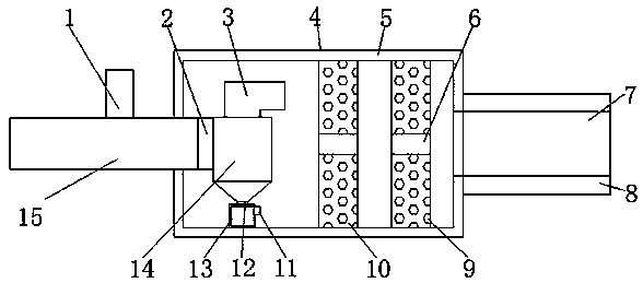
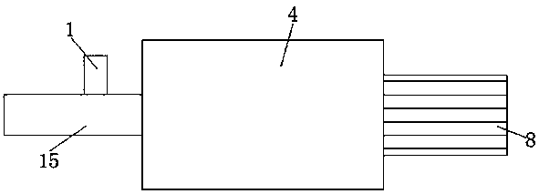
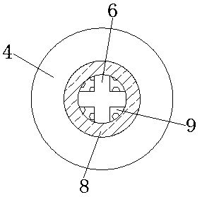
The invention discloses an automobile exhaust purifier. The automobile exhaust purifier comprises a shell; an exhaust pipe and an air charging pipe are separately installed at the two sides of the shell; cooling fins are arranged outside the exhaust pipe; the top of the air charging pipe is provided with an oxygen sensor connecting port; a heat insulating layer is arranged at the inner side of theshell; a second exhaust catalyzing plate, a first exhaust catalyzing plate and a cyclonedust collector are sequentially installed inside the shell; the second exhaust catalyzing plate, the first exhaust catalyzing plate and the cyclonedust collector are positioned at the same straight line; and the first exhaust catalyzing plate is positioned between the second exhaust catalyzing plate and thecyclone dust collector. The automobile exhaust purifier disclosed by the invention is provided with the cyclone dust collector and a dust collecting box so that carbon particles cannot be adhered to the purifier; a heat absorbing plate is arranged for making the heat inside the catalyzing plates rise quickly so that the catalyzing plates do not absorb heat too slowly, and thus the exhaust can be easily purified after an automobile is just started; and the cooling fins are arranged for preventing a passenger which walks behind the automobile from being scalded by the exhaust when the automobilestops on a road.
Description
technical field [0001] The invention belongs to the technical field of auto parts, and in particular relates to an auto exhaust purifier. Background technique [0002] Automobile exhaust purifier is a purifier that can convert harmful gases such as CO, HC and NOx emitted from automobile exhaust into harmless carbon dioxide, water and nitrogen through oxidation and reduction. When the high-temperature automobile exhaust passes through the purification device, the purifier will enhance the activity of the three gases CO, HC and NOx, and promote them to undergo a certain oxidation-reduction chemical reaction, and the three harmful gases will become harmless gases, so that the automobile exhaust can be purified. purify. [0003] However, there are some defects in the use of automobile exhaust purifiers on the market. For example, there are carbon particles in the exhaust gas, which are easy to adhere to the device, which reduces the working efficiency of the device. When the ca...
Claims
Application Information
Patent Timeline
Application Date:The date an application was filed.
Publication Date:The date a patent or application was officially published.
First Publication Date:The earliest publication date of a patent with the same application number.
Issue Date:Publication date of the patent grant document.
PCT Entry Date:The Entry date of PCT National Phase.
Estimated Expiry Date:The statutory expiry date of a patent right according to the Patent Law, and it is the longest term of protection that the patent right can achieve without the termination of the patent right due to other reasons(Term extension factor has been taken into account ).
Invalid Date:Actual expiry date is based on effective date or publication date of legal transaction data of invalid patent.

