
Cross-flow fan and air conditioner

A technology of cross-flow blades and blades, which is applied in the field of cross-flow blades, and can solve problems such as large injection mold volume, large impact at the same frequency of the volute tongue, and unnatural air-conditioning sound.

Pending Publication Date: 2018-04-20
NINGBO LANGDI IMPELLER MACHINERY
View PDF6 Cites 2 Cited by
  • Summary
  • Abstract
  • Description
  • Claims
  • Application Information

AI Technical Summary

Problems solved by technology

The deficiencies of the cross-flow fan blades of the existing structure are: 1. The amount of injection molds is large, and one diameter specification needs 3 pairs of injection molds to complete, which are steel shaft end wheel mold, middle wind wheel mold and rubber end impeller mold, n Each diameter specification requires 3n pairs of injection molds, and the production cost is high; 2. The welding positioning accuracy of the rubber bushing assembly and the rubber end wheel is not easy to control, which affects the concentricity of the cross-flow fan blade, resulting in large vibration and noise of the cross-flow fan blade
In addition, the inclination angle of the blades on each middle plate on the existing cross-flow blades and the same central angle of the adjacent blades, the air pressure before and after the airflow of the cross-flow blades passes through the blades twice is high, and the sound of the air outlet of the air conditioner using the above-mentioned cross-flow blades Unnatural, the impact of the blade on the volute tongue is large at the same frequency, and the rotation noise of the fan blade is large

Method used


Image

  • Cross-flow fan and air conditioner
  • Cross-flow fan and air conditioner
  • Cross-flow fan and air conditioner

Examples


Embodiment 1

[0024] Such as Figure 5 , Image 6 , Figure 7 , Figure 8 , Figure 9 , Figure 10 with Figure 11 The shown cross-flow vane includes a steel shaft end wheel 4 , multiple middle wind wheels 5 and a rubber end impeller 6 .

[0025] The steel shaft end wheel 4 includes a steel shaft disc 41 and a metal steel shaft 42, the steel shaft disc 41 is provided with a welding groove 43, the metal steel shaft 42 is inlaid in the middle of the steel shaft disc 41, and the metal steel shaft 42 is used to connect the air conditioner. bearings in the track.

[0026] The middle wind wheel 5 comprises a middle plate 51 and a plurality of blades 52 connected thereto, the blades 52 are 31-39 pieces, the blade 52 rear end is integrally injection molded with the middle plate 51 front ends, and the middle part of each middle plate 51 is provided with There is a through hole 54, and the inner end of the middle plate 51 is provided with a circular groove 53, and the circular groove 53 is ste...

Embodiment 2

[0040] An air conditioner, which adopts the cross-flow fan blade of the above-mentioned embodiment 1, reduces the vibration of the cross-flow fan blade during operation, can reduce the noise and vibration of the whole machine, the noise is low, and the sound of the air outlet of the air conditioner is more natural and comfortable.


PUM


Abstract

The invention relates to an air-conditioning accessory. A cross-flow fan comprises a steel shaft end wheel, a plurality of medium wind wheels and a rubber end impeller. The inner end of a middle discis provided with a circular groove. The rubber end impeller comprises a wheel disc and a rubber shaft sleeve assembly. The rubber shaft sleeve assembly is fixed at the middle of the wheel disc in an embedded mode. The diameter of the wheel disc is matched with the diameter of the circular groove. The front end of the wheel disc is welded to and fixed to the circular groove. The rubber end impelleris fixed in the circular groove in a medium disc of the medium wind wheel at the last end. The angles of the blade inclination angle of any adjacent blades are different. The angles of central anglesof the adjacent blades are different. The cross-flow fan has the advantages of being novel in structure, low in production cost, low in vibration, low in noise and natural in wind outlet sound.

Description

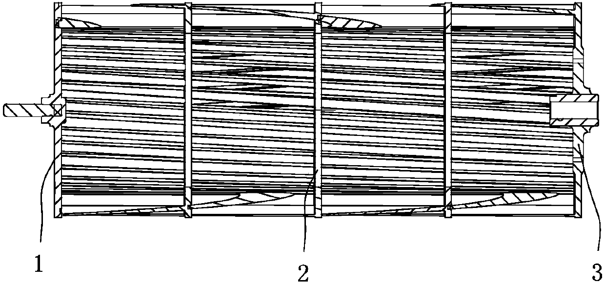
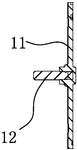
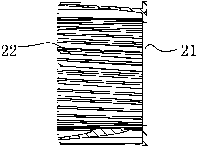
technical field [0001] The invention relates to an air conditioner accessory, in particular to a cross-flow fan blade. Background technique [0002] The cross-flow fan blade is one of the important accessories in the air conditioner. Such as figure 1 As shown, the existing cross-flow fan blade is usually made of a steel shaft end wheel 1, several mid-wind wheels 2 and a rubber end impeller 3 through ultrasonic welding. Steel shaft end wheel 1 such as figure 2 As shown, it includes a steel shaft disc 11 and a metal steel shaft 12. The steel shaft disc is provided with a welding groove, and the middle of the steel shaft disc is embedded with a metal steel shaft, and the steel shaft is connected to the bearing in the air-conditioning duct. stroke wheel 2 as image 3 As shown, it is composed of an annular central plate 21 and a plurality of blades 22 by integral injection molding. The rear end of the blade is connected with the front end of the circular central plate as a w...

Claims


Application Information

Patent Timeline
IPC IPC(8): F04D29/30F04D29/28F04D29/66F24F1/00
CPCF04D29/282F04D29/30F04D29/663F04D29/666F04D29/668F24F1/0025
Inventor 高文铭柴水华韩小红周会中
Owner NINGBO LANGDI IMPELLER MACHINERY
Learn More