Pneumatic parking brake

A parking brake and brake wheel technology, applied in the direction of brake type, axial brake, brake parts, etc., can solve the problems of high brake release pressure, oil leakage polluting the environment, low friction coefficient, etc., and achieve less wear And heat, clean energy, good effect of pipeline

Pending Publication Date: 2018-04-20
XUZHOU KEYUAN HYDRAULIC
View PDF0 Cites 4 Cited by
  • Summary
  • Abstract
  • Description
  • Claims
  • Application Information

AI Technical Summary

Problems solved by technology

[0002] At present, most of the parking brakes are installed between the transmission case and the drive axle, and are used individually; through the force generated by the spring group, the friction plate is pressed to realize the parking brake; hydraulic oil is pressed into the brake cylinder to push the piston further The spring is compressed so that there is a gap between the friction plates to move relative to each other, so as to realize the parking release, that is, when the vehicle is moving, the friction plates are always moving relative to each other, and each friction plate is always rubbing against each other, which will generate more heat. ; Therefore, wet brakes are often used, and seals are installed on the brakes, and gear oil is used to lubricate and cool down the friction plates to prevent overheating and sintering of the friction plates; while the friction coefficient between the friction plates of wet brakes is relatively low, in order to have enough parking torque, it is necessary to More sets of friction plates and more sets of springs; more friction plates will generate more heat, which is harmful to brake heat dissipation and brake seals; more spring sets require a comparison of brake release pressure If the piston ring area is large, the parking brake can only be released by hydraulic pressure; if the seal is not tight, oil leakage will occur and pollute the environment

Method used


Image

  • Pneumatic parking brake
  • Pneumatic parking brake

Examples


Embodiment Construction

[0016] The present invention will be further described below according to the accompanying drawings and embodiments.

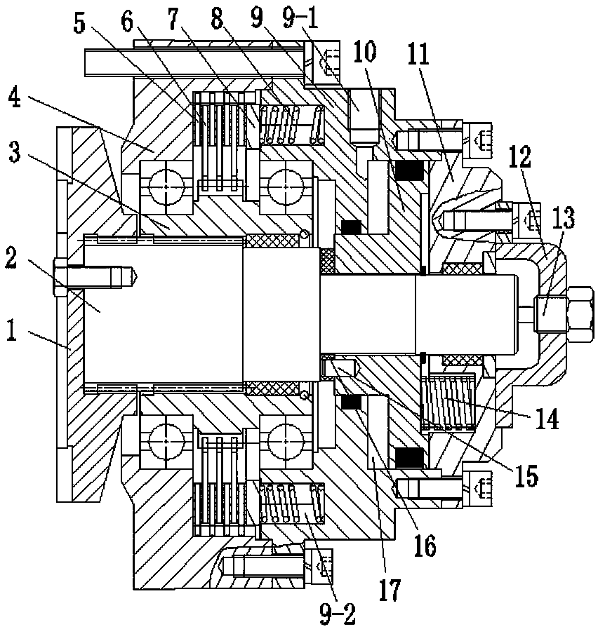
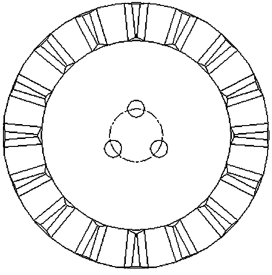
[0017] like figure 1 and figure 2 As shown, a pneumatic parking brake includes a flange 1, a brake shaft 2, a brake wheel 3, a brake housing 4, a piston housing 9, a piston 10 and a spring seat 11, and the brake wheel 3 is located on the brake shaft 2 and the brake shaft 2 can move axially along the brake wheel 3; the brake housing 4 and the piston housing 9 are fixed by bolts, and the brake housing 4 and the brake wheel 3 and the piston housing 9 and the brake wheel 3 are fitted with bearings, and the bearing between the brake housing 4 and the brake wheel 3 is formed by the inner hole shoulder of the brake housing 4 and the outer circle of the brake wheel 3. The shaft shoulder is limited; the bearing between the piston housing 9 and the brake wheel 3 is limited by the corresponding shaft shoulder of the inner hole of the piston housing 9 and the outer cir...


PUM


Abstract

The invention belongs to the field of engineering machinery, and in particular relates to a parking brake. The brake wheel is arranged on the brake shaft and the brake shaft can move axially along the brake wheel; the brake housing and the piston housing are fixed by bolts, and A brake assembly that restricts the rotation of the brake wheel is provided between the moving housing and the piston housing; the flange is fixed on the end surface of the brake shaft close to the brake housing; the spring seat is fixed on the piston housing, and the piston is sleeved on the on the brake shaft, and can move axially between the piston housing and the spring seat. The spring seat is set with a clutch spring group that pushes the piston to move to the flange side. The air inlet of the axial gap between the pistons; the outer end surface of the flange is provided with a tooth shape matched with the shaft end surface of the axle wheel drive shaft. The friction plates of the present invention do not generate or generate relatively little wear and heat, and do not need to cool down and lubricate; and because they do not directly act on the friction plates, the pressure to release the brake is small, so the air source power is used, which is energy-saving and environmentally friendly.

Description

technical field [0001] The invention belongs to the field of engineering machinery, and in particular relates to a parking brake. Background technique [0002] At present, most of the parking brakes are installed between the transmission case and the drive axle, and are used individually; through the force generated by the spring group, the friction plate is pressed to realize the parking brake; hydraulic oil is pressed into the brake cylinder to push the piston further The spring is compressed so that there is a gap between the friction plates to move relative to each other, so as to realize the parking release, that is, when the vehicle is moving, the friction plates are always moving relative to each other, and each friction plate is always rubbing against each other, which will generate more heat. ; Therefore, wet brakes are often used, and seals are installed on the brakes, and gear oil is used to lubricate and cool down the friction plates to prevent overheating and si...

Claims


Application Information

Patent Timeline
Patent Type & Authority Applications(China)
IPC IPC(8): F16D55/26F16D65/14F16D65/02F16D66/00F16D121/04F16D125/06F16D125/08
CPCF16D55/26F16D65/14F16D2065/1388F16D2066/003F16D2121/04F16D2125/06F16D2125/08
Inventor 黄春有丁虽要黄建革纪传雷韩永进韩华
Owner XUZHOU KEYUAN HYDRAULIC
Why Eureka
Try Eureka