Oil returning gas removal device and lubricating oil system

A gas device and lubricating oil technology, applied in lubricating oil containers, lubricating parts, engine lubrication, etc., can solve the problems of reduced lubricating oil transportation capacity, high bearing bush temperature, abnormal vibration and noise of the system, etc., to avoid oil return and rolling , Guarantee the effect of lubrication, reduce the effect of cavitation noise

Active Publication Date: 2018-04-20
NO 719 RES INST CHINA SHIPBUILDING IND
View PDF3 Cites 2 Cited by
  • Summary
  • Abstract
  • Description
  • Claims
  • Application Information

AI Technical Summary

Problems solved by technology

The diameters of these bubbles are mainly distributed between 0.3 and 0.5 mm. Due to the small diameter of the bubbles, it is difficult for the bubbles to float up to the surface of the fuel tank through their own buoyancy to collect and remove them. In addition, the circulation rate of the fuel tank is limited, so these tiny bubbles are very difficult. Quickly spreads to all corners of the tank, making it more difficult to remove
Under normal circumstances, after a long period of operation, the air content of the lubricating oil in the lubricating oil system of the steam turbine and reducer is about 8-10%. These air bubbles seriously affect the normal operation of the lubricating oil system, resulting in the following adverse consequences: (1) The delivery capacity of...

Method used


Image

  • Oil returning gas removal device and lubricating oil system
  • Oil returning gas removal device and lubricating oil system
  • Oil returning gas removal device and lubricating oil system

Examples


Embodiment Construction

[0032] The present invention will be further described in detail below with reference to the accompanying drawings and specific embodiments.

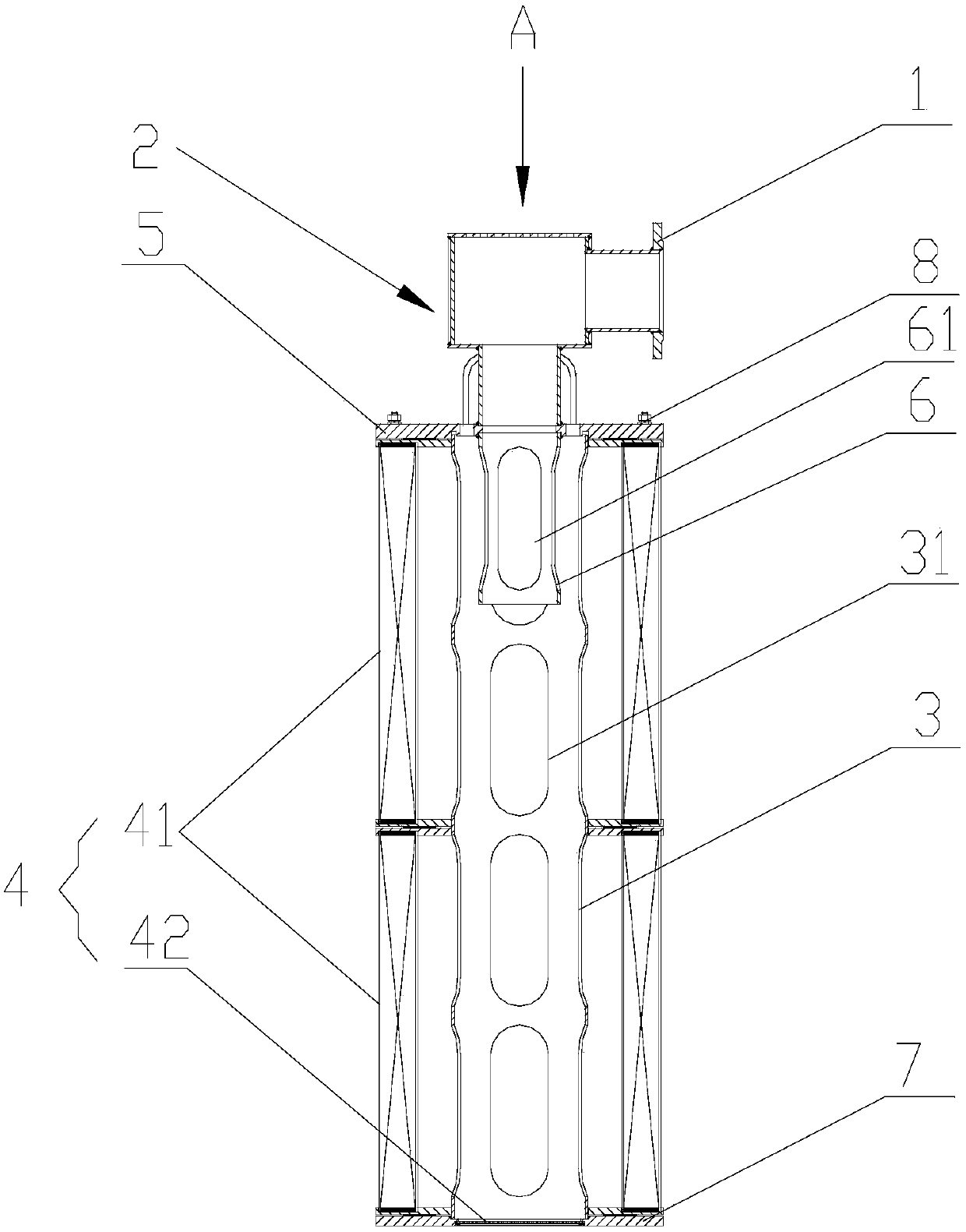
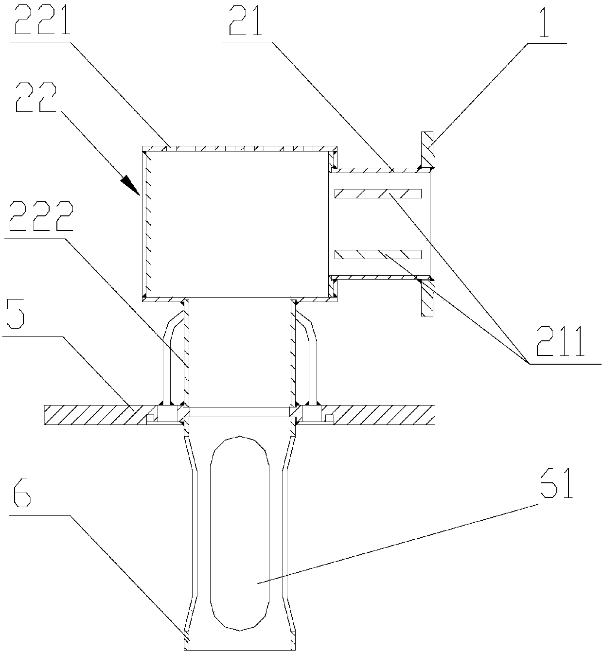
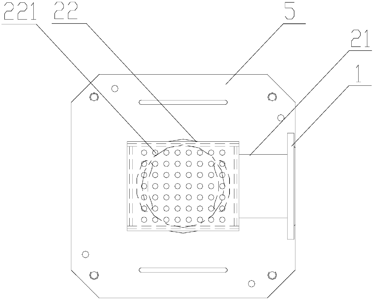
[0033] see figure 1 As shown, the embodiment of the present invention provides an oil return and degassing device, which is arranged in an oil tank of a lubricating oil system. The connecting piece 1 is used to install the oil return and degassing device to the oil return hole on the inner wall of the oil tank, and the connecting piece 1 can be a flange plate, and the flange plate is matched with the oil return hole. The inlet end of the oil return pipe assembly 2 is connected to the connector 1, the sleeve 3 is arranged at the outlet end of the oil return pipe assembly 2, and forms a continuous pipeline with the oil return pipe assembly 2, and a plurality of oil passage holes are opened around the cylinder wall of the sleeve 3 31. The oil passage holes 31 are arranged at intervals along the length direction and the circumferential dir...


PUM


Abstract

The invention discloses an oil returning gas removal device and a lubricating oil system, and relates to the technical field of power devices. The oil returning gas removal device is arranged in an oil tank of the lubricating oil system and comprises a connecting part, an oil returning pipe assembly, a sleeve and a filter assembly; the connecting part is used for mounting the oil returning gas removal device in an oil returning hole in the inner wall of the oil tank, the inlet end of the oil returning pipe assembly is connected with the connecting part, the sleeve is arranged at the outlet endof the oil returning pipe assembly, the sleeve and the oil returning pipe assembly form a continuous pipeline, multiple oil passing holes are formed in the periphery of the wall of the sleeve, the filter assembly is detachably arranged on the circumferential outer side and the bottom of the sleeve, and the filter assembly is provided with a filter net with the hole diameter smaller than 0.3 mm. Oil returning turning over and bubbles generated by traditional gravity oil returning can be avoided, the filter net of the filter assembly can effectively separate bubbles with the diameter above 0.3mm in the oil returning process, the gas containing amount in lubricating oil can be effectively reduced, the lubricating effect of the lubricating oil is ensured, and cavitation noise caused by gas containing of the lubricating oil can be reduced.

Description

technical field [0001] The invention relates to the technical field of power devices, in particular to an oil return and degassing device and a lubricating oil system. Background technique [0002] The lubricating oil system of the steam turbine and the reducer is connected to the atmosphere, and the oil return will bring the gas into the oil tank of the lubricating oil system. The diameter of these bubbles is mainly distributed between 0.3 and 0.5mm. Due to the small diameter of the bubbles, it is difficult for the bubbles to float up to the surface of the fuel tank by their own buoyancy to gather and remove them. In addition, the circulation rate of the fuel tank is limited, which makes these tiny bubbles very difficult. It quickly spreads to all corners of the fuel tank, making it more difficult to remove. Under normal circumstances, after long-term operation, the air content of the lubricating oil in the lubricating oil system of the steam turbine and the reducer is abo...

Claims


Application Information

Patent Timeline
IPC IPC(8): F16N39/00F16N39/06F16N19/00
CPCF16N19/00F16N39/002F16N39/06F16N2039/007
Inventor 陈景明龙成毅邵燕孟海波赵旭峰王春国陈勇刘修良
Owner NO 719 RES INST CHINA SHIPBUILDING IND
Why Eureka
Try Eureka