Tool path generating method of propeller blade processing

A propeller and tool path technology, which is applied in the field of tool path trajectory generation for machining propeller blades by CNC machine tools, can solve problems such as multiple tool paths, and achieve the effect of reducing processing costs and high automation.

Active Publication Date: 2018-04-20
JIANGSU UNIV OF SCI & TECH
View PDF5 Cites 5 Cited by
  • Summary
  • Abstract
  • Description
  • Claims
  • Application Information

AI Technical Summary

Problems solved by technology

The above-mentioned tool path planning method does not carry out detailed area division on the processing surface, and more redundant tool paths are likely to be generated in the process of tool path planning. It is best to automatically implement a plan to improve the intelligence of the entire planning process

Method used


Image

  • Tool path generating method of propeller blade processing
  • Tool path generating method of propeller blade processing
  • Tool path generating method of propeller blade processing

Examples


Embodiment Construction

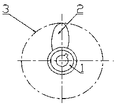
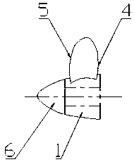
[0029] In the present invention, firstly, the curved surface of the propeller blade is divided into pieces to obtain several sub-curved surfaces. Secondly, the tool path planning is carried out for each sub-surface. In the process of tool path planning for each sub-surface, the appropriate tool-feeding direction, line spacing direction, line spacing and step accuracy are selected to generate the tool contact trajectory of each surface and Calculate and generate tool point trajectory. Finally, supplementary processing is performed on the boundary part of each sub-surface. The specific implementation steps are as follows:

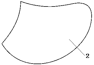
[0030] Such as image 3 with Figure 4 As shown, first of all, for image 3 The blade surface 2 of the propeller blade is segmented, and the blade surface 2 of the propeller blade is divided into different sub-surface areas processed by numerical control. When the sub-surface area is segmented, the concavity and convexity of each point in each sub-surface...


PUM


Abstract

The invention discloses a tool path generating method of propeller blade processing in the field of numerical-control machine tool processing. A curved surface of a propeller blade is segmented into sub curved surfaces, tool path planning is carried out on each sub curved surface, in the tool path planning process of the sub curved surfaces, proper feeding direction, line spacing direction, line spacing and step precision are selected, cutter contact tracks of the sub curved surfaces are generated, cutter position tracks are calculated and generated, and the boundary portions of the sub curvedsurfaces are processed complementarily. The whole planning process is realized intelligently, the whole tool path planning process is programmable and easier to conclude into a unified algorithm andfurther to realize higher automatic degree, the planned tool path is suitable for a tri-axial machine tool, the quality of processing surfaces of the propeller blade is improved, and formation of redundant tool paths is reduced.

Description

technical field [0001] The invention relates to the technical field of numerically controlled machine tool processing, in particular to a method for generating a tool path track for machining propeller blades by using a numerically controlled machine tool, using basic theoretical knowledge of curved surface curve modeling. Background technique [0002] The structure of the propeller blade is as figure 1 with figure 2 As shown, it includes propeller hub 1, propeller blade surface 2 and hub cap 6. When the propeller rotates, its blade tip track circle is tip circle 3. The main processing content of the propeller blade is the propeller blade surface 2, therefore, the tool path planning of the propeller blade is the tool path planning of the propeller blade surface 2. [0003] In the existing processing methods, when processing complex free-form surfaces such as propeller blade surface 2, the isoparametric line method or the parallel section method is generally used to genera...

Claims


Application Information

Patent Timeline
Patent Type & Authority Applications(China)
IPC IPC(8): G05B19/19
CPCG05B19/19G05B2219/35349
Inventor 张辉李磊磊张胜文朱鹏费天鸣欧联春朱成顺方喜峰
Owner JIANGSU UNIV OF SCI & TECH
Why Eureka
Try Eureka