Hierarchical system integration design modeling method

A system integration and modeling method technology, applied in the field of hierarchical system integration design and modeling, can solve problems such as single goal and lack of description model, and achieve the effect of improving efficiency

Inactive Publication Date: 2018-04-20
BEIHANG UNIV
View PDF6 Cites 6 Cited by
  • Summary
  • Abstract
  • Description
  • Claims
  • Application Information

AI Technical Summary

Problems solved by technology

[0004] The existing conceptual design description model has the characteristics of diversity of expression and single goal, and lacks a unified description model that can combine different aspects of characteristic information (requirements, functions, behaviors, structures, etc.) in the design to form an integrated produ

Method used


Image

  • Hierarchical system integration design modeling method
  • Hierarchical system integration design modeling method
  • Hierarchical system integration design modeling method

Examples


specific Embodiment approach 1

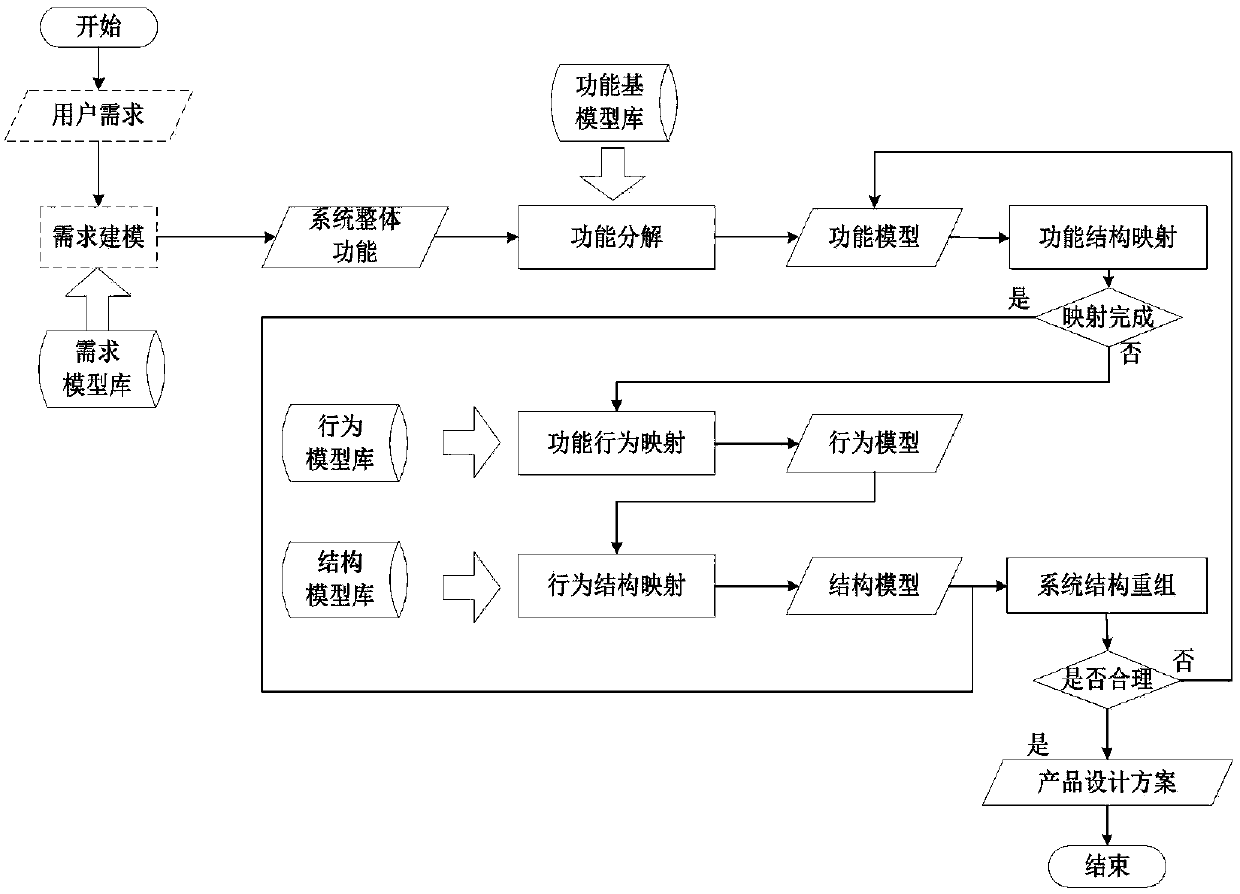
[0032] Specific implementation mode one: combine figure 1 As shown, this embodiment is a hierarchical system integration design modeling method, including the following steps:

[0033] Pre-defined steps of conceptual design model library: according to the design tasks of product systems in different disciplines, construct and import the required model library, function model library, behavior model library and structure model library, and use SysML to graphically express the model library;

[0034] The steps of requirements classification modeling: graphical modeling of system requirements from the overall perspective of the system;

[0035] The steps of functional requirements analysis based on use cases: From the perspective of users, identify the main functions of the product through use case analysis and define the system boundaries;

[0036] Steps of system function modeling: Designers analyze and confirm the type and quantity of input and output streams for specific sit...

specific Embodiment approach 2

[0038] Embodiment 2: This embodiment is a further limitation of Embodiment 1, wherein the steps of constructing and importing the demand model library used according to the design tasks of product systems in different disciplines are:

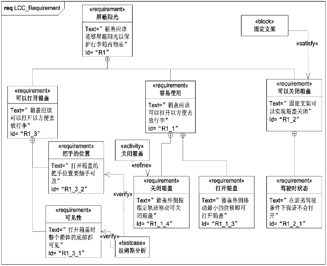
[0039] Model the document-style requirements described in natural language, directly build a requirement model library in a modeling tool that supports SysML language, and classify and store the requirement model library in the form of packages according to functional requirements, operation requirements, performance requirements, and interface requirements In a separate format-specific file, each requirement element is represented by two basic attributes "Id" and "Text".

specific Embodiment approach 3

[0040] Embodiment 3: This embodiment is a further limitation of Embodiment 2, wherein the steps of constructing and importing the functional model library used according to the design tasks of product systems in different disciplines are as follows:

[0041] Decompose the basic atomic function into a four-tuple, including function ID, input flow f_in, function element p, output flow f_out, and use the function expression of "function element + flow object" to subdivide the function element into a three-layer structure Expressed, the flow is divided into three categories: material, energy and signal.


PUM


Abstract

The invention relates to a hierarchical system integration design modeling method. Through five steps of concept design model library pre-definition, demand classification modeling, case-based function demand analysis, system function modeling, and function-behavior-structure mapping of multiple paths, unified description of demand, function, behavior and structure information of a system conceptdesign model is realized. The method has the advantages of formalization, object orientation and graphical processing; and the system concept design efficiency can be improved.

Description

technical field [0001] The invention belongs to the research content of the field of computer-aided system design, and more specifically, the invention relates to a modeling method for hierarchical system integration design. Background technique [0002] The systematic method research of complex product development is the product of the combination of product design and system engineering. The steps form a detailed process method. A typical system development process includes four stages: clarifying tasks, explaining and defining design tasks; conceptual design, defining the overall functions and sub-functions of the product system, and forming a functional structure; preliminary design and detailed design, thereby generating a design scheme. [0003] Although in different engineering fields, there are many process models that are different from the tasks in the above conceptual design process, such as the combination of top-down design process and bottom-up integration ver...

Claims


Application Information

Patent Timeline
IPC IPC(8): G06F17/50
CPCG06F30/20G06F2111/20
Inventor 刘继红王树德
Owner BEIHANG UNIV
Why Eureka
Try Eureka