
Circuit for improving transmission characteristics of optocoupler

A technology of transmission characteristics and optocoupler, applied in the direction of logic circuit coupling device, logic circuit connection/interface layout, etc., can solve the problems of large time difference of light-emitting tube, decrease of performance index, increase of cost, etc., to improve transmission performance and delay time. The effect of less time and improved accuracy

Pending Publication Date: 2018-04-20
NANJING NEW POWER ELECTRIC
View PDF0 Cites 1 Cited by
  • Summary
  • Abstract
  • Description
  • Claims
  • Application Information

AI Technical Summary

Problems solved by technology

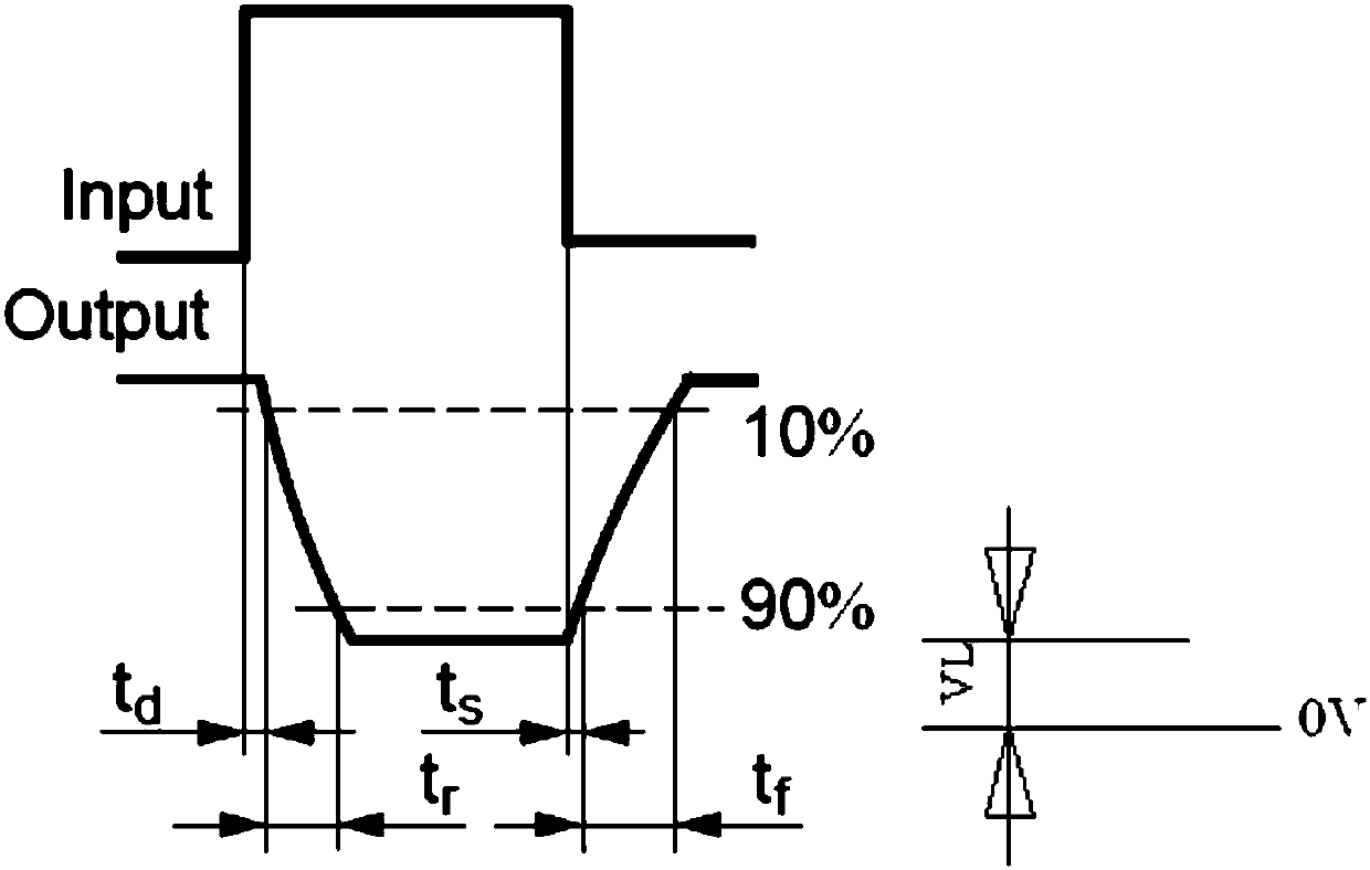
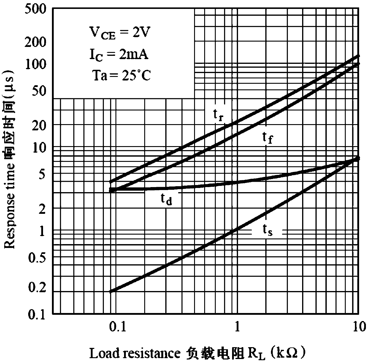
but with t s , t f Compared with the difference of t d , t r The difference is not big, that is to say, the time difference between the rising and falling edges of the output is relatively large when the internal light-emitting tube is turned on and off, and they are not proportional to the output amplitude;
[0008] 5) The output usually uses a fixed value as the judgment threshold of high and low levels, so the time of outputting high and low levels will change greatly compared with the input, so that the overall performance index will be greatly reduced
This will have a greater impact on the overall performance
Although using a high-speed optocoupler or a special optocoupler will be slightly better on these problems, it still cannot solve these problems well, and at the same time the cost will increase a lot

Method used


Image

  • Circuit for improving transmission characteristics of optocoupler
  • Circuit for improving transmission characteristics of optocoupler
  • Circuit for improving transmission characteristics of optocoupler

Examples


Embodiment Construction

[0026] like Figure 4 As shown, the present invention discloses a circuit for improving the transmission characteristics of the optocoupler, including a floating threshold circuit and a comparator following the output value of the optocoupler, the output terminal of the optocoupler and the positive input terminal of the comparator or the negative input terminal of the comparator The output terminal of the floating threshold circuit following the output value of the optocoupler is connected to the negative input terminal of the corresponding comparator or the positive input terminal of the comparator. The output signal of the optocoupler changes from the highest or lowest level to a certain value of the total amplitude. The level value of the proportional value is used as the floating threshold following the output value of the optocoupler. When the output signal of the optocoupler is greater than the floating threshold following the output value of the optocoupler, the level ou...


PUM


Abstract

The invention relates to the technical field of optocoupler application circuits, in particular to a circuit for improving the transmission characteristics of an optocoupler. The circuit comprises a floating threshold circuit following an optocoupler output value, and a comparator, an output end of the optocoupler is connected to a positive input end of the comparator or a negative input end of the comparator, the output end of the floating threshold circuit following the optocoupler output value is connected with the negative input end of the comparator or the positive input end of the comparator, an optocoupler output signal changes from the highest or lowest level to a level value of a certain proportion value of the total amplitude to serve as a floating threshold of following the optocoupler output value, and when the optocoupler output signal is greater than the floating threshold of following the optocoupler output value, the level output end of the comparator is overturned, andthus corresponding high and low levels are output. The circuit improves the transmission characteristics of the optocoupler, so that the transmission rate of the optocoupler is greatly improved, theproduct cost is reduced, and more importantly, the reliability of the optocoupler product is greatly improved.

Description

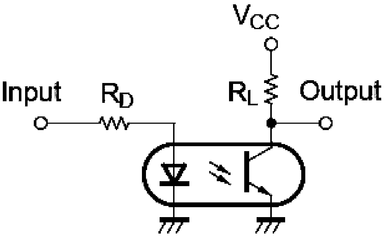
technical field [0001] The invention relates to the technical field of optocoupler application circuits, in particular to a circuit for improving the transmission characteristics of optocouplers. Background technique [0002] Optical coupler (optical coupler, abbreviated as OC) is also called opto-isolator or opto-coupler, opto-coupler for short. Ordinary optocouplers have been widely used in signal transmission and isolation circuits and products due to their low cost, many varieties, and many manufacturers. [0003] figure 1 Typical application circuit for optocoupler, figure 2 for figure 1 The input and output waveform diagrams, but in application, due to the inherent characteristics of the optocoupler itself, its transmission characteristics are poor, especially when the transmission frequency reaches 10KHz, it can no longer transmit normally in the entire temperature range of the device. It is used to transmit signals with different duty ratios, such as PWM signals...

Claims


Application Information

Patent Timeline
Patent Type & Authority Applications(China)
IPC IPC(8): H03K19/0175
CPCH03K19/017572
Inventor 董健董伟陈悦
Owner NANJING NEW POWER ELECTRIC
Learn More