Laparoscopic surgical robot structure centered on laparoscope-holding arm
A surgical robot and laparoscopic technology, applied in the field of medical devices, can solve the problems of restricting the development of minimally invasive surgery, unsatisfactory visual effects, difficult to popularize and apply, etc. Effect
- Summary
- Abstract
- Description
- Claims
- Application Information
AI Technical Summary
Problems solved by technology
Method used
Image

Examples
Embodiment 1
[0020] See figure 1 , figure 2 and image 3 as shown,
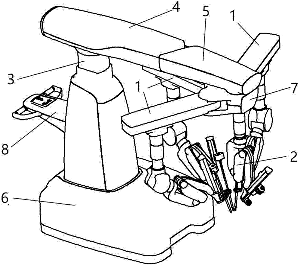
[0021] figure 1 It is a structural diagram of a laparoscopic surgical robot centered on the mirror-holding arm in this embodiment;
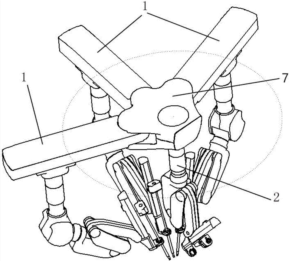
[0022] figure 2 It is a three-dimensional principle view of a laparoscopic surgery robot structure centered on the mirror-holding arm in this embodiment;
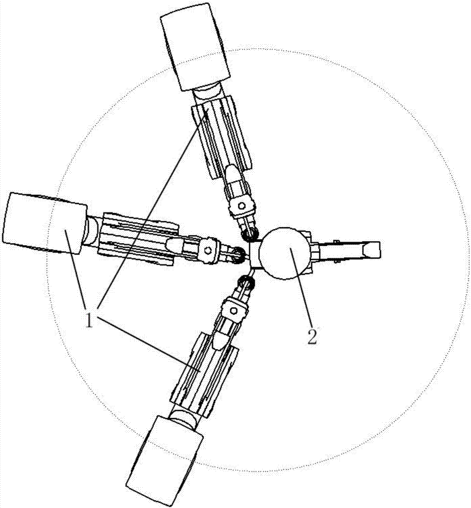
[0023] image 3 It is a two-dimensional top view of the structure of a laparoscopic surgical robot centered on the mirror-holding arm in this embodiment.
[0024] This embodiment provides a laparoscopic surgery robot structure centered on the mirror arm, which includes an instrument arm 1, a mirror arm 2, a lifting column 3, a first support arm 4, a second support arm 5, a base 6, a rotating Disc 7 and armrest 8. The lifting column 3 is connected with the base 6, which can realize the process of raising and lowering the whole equipment; the handrail 8 is connected with the lifting column 3, and is used to realize the push-pull p...
Embodiment 2
[0033] See Figure 6 as shown,
[0034] Figure 6 It is a structural diagram of a laparoscopic surgical robot centered on the mirror-holding arm in this embodiment.
[0035] This embodiment provides a laparoscopic surgery robot structure centered on the mirror arm, which includes an instrument arm 1, a lifting column 3, a first support arm 4, a second support arm 5, a base 6, a rotating disk 7 and an armrest 8 . The lifting column 3 is connected with the base 6, which can realize the process of raising and lowering the whole equipment; the handrail 8 is connected with the lifting column 3, and is used to realize the push-pull process of the whole equipment; the first The support arm 4 is connected with the lifting column 3, and can freely rotate around the lifting column 3; the second support arm 5 is connected with the first support arm 4, and the second support arm 5 is relatively The first support arm 4 can rotate freely, the rotating disc 7 is connected with the second...
PUM
 Abstract
Description
Claims
Application Information
PatSnap Eureka turns technology decisions into work you can execute. Powered by our Innovation Knowledge Graph, it runs expert workflows across engineering, life sciences, materials and intellectual property. Get your review-ready output in minutes.


