Piezoelectric stick-slip micro nano angular displacement platform and driving method thereof

A driving method and angular displacement technology, which is applied in the direction of large fixed members, metal processing machinery parts, metal processing equipment, etc., can solve the problems of large structure size, high production cost, and low positioning accuracy, and achieve lightweight cost and simple assembly , The effect of high positioning accuracy

Active Publication Date: 2018-04-24
CHANGCHUN UNIV OF TECH
View PDF8 Cites 5 Cited by
  • Summary
  • Abstract
  • Description
  • Claims
  • Application Information

AI Technical Summary

Problems solved by technology

[0005] In order to solve the technical problems of low positioning accuracy, large structural size and high production cost in the existing angular displacement positioning platform, the present invention discloses a piezoelectric stick-slip micro-nano angular displacement platform and its driving method

Method used


Image

  • Piezoelectric stick-slip micro nano angular displacement platform and driving method thereof
  • Piezoelectric stick-slip micro nano angular displacement platform and driving method thereof
  • Piezoelectric stick-slip micro nano angular displacement platform and driving method thereof

Examples


specific Embodiment approach 1

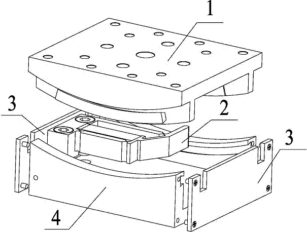
[0031] Specific implementation mode one: combine Figure 1~Figure 10 Describe this embodiment. This embodiment provides a specific implementation of an oblique lever amplified piezoelectric stick-slip micro-nano angular displacement stage. The specific implementation is described as follows:

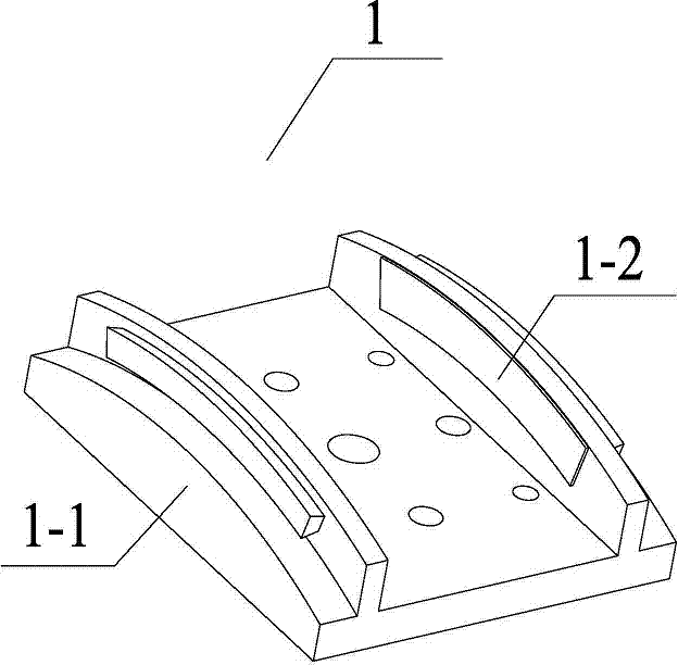
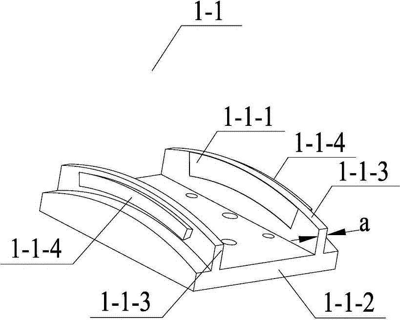
[0032] The oblique lever amplified piezoelectric stick-slip micro-nano angular displacement stage is composed of a sliding table 1, a lateral drive device 2, a baffle 3 and a base 4; the sliding table 1 passes through an arc-shaped dovetail slider 1 -1-4 and the arc-shaped dovetail groove 4-1 are installed on the upper end of the base 4, and the lateral drive device 2 is fixedly installed on the base through the screw connection of the fixing bolt I2-5 and the installation threaded hole II4-3. In the seat 4, the two baffles 3 are respectively fixed and installed on both sides of the base 4 through the screw connection of the fixing bolt II3-2 and the installation threaded hole III4-4. ...

specific Embodiment approach 2

[0037] Specific implementation mode two: combination Figure 11~12 Describe this embodiment. This embodiment provides a specific embodiment of a ladder-shaped lever-amplified piezoelectric stick-slip micro-nano angular displacement stage. The specific structural composition of the lever amplifying mechanism 2-1 is different.

[0038] The lever amplifying mechanism 2-1 utilizes a stepped lever 2-1-9 to amplify displacement, and one side of the lever amplifying mechanism 2-1 is provided with a semicircular flexible hinge 2-1-1 and a connecting rod I2-1- 2. Both ends of the connecting rod I2-1-2 are respectively connected to a semicircular flexible hinge 2-1-1, and the other side of the lever amplification mechanism 2-1 is provided with a circular flexible hinge 2-1-8 and the connecting rod II 2-1-5, the front end of the connecting rod II 2-1-5 is connected to a circular flexible hinge 2-1-8, the semicircular flexible hinge 2-1-1 and the circular flexible hinge 2 -1-8 has fille...

specific Embodiment approach 3

[0039] Specific implementation mode three: combination Figure 13~14 Describe this embodiment. This embodiment provides a specific embodiment of a parallel lever amplified piezoelectric stick-slip micro-nano angular displacement stage. Its structural composition, connection method, and positioning method are the same as those of the first and second embodiments. The difference is that The specific structural composition of its lever amplifying mechanism 2-1 is different.

[0040] The lever amplifying mechanism 2-1 uses parallel levers 2-1-11 to amplify the displacement, and one side of the lever amplifying mechanism 2-1 is provided with a semicircular flexible hinge 2-1-1 and a connecting rod I2-1-2 , the two ends of the connecting rod I2-1-2 are respectively connected to a semicircular flexible hinge 2-1-1, and the other side of the lever amplification mechanism 2-1 is provided with a semicircular flexible hinge 2-1-1 and the connecting rod II 2-1-5, the front end of the con...


PUM


Abstract

The present invention relates to a piezoelectric stick-slip micro nano angular displacement platform and a driving method thereof, and the problems that an existing angular displacement positioning platform is low in positioning precision, large in structure size and high in cost are solved. The angular displacement platform is composed of a sliding stand, a lateral driving device, baffle plates and a pedestal. Due to lever equivalent rotation of a lever amplification mechanism, a driving foot is urged to generate a lateral displacement greater than an original deformation of a piezoelectric ceramics stack; motion conversion is achieved by using an arc-shaped dovetail groove, so that rectilinear motion output by the lateral driving device is converted to required curvilinear motion; and the designed lever amplification mechanism is simple to assemble and easy to adjust, and is replaceable. Compared with the prior art, the piezoelectric stick-slip micro nano angular displacement platform has the characteristics of high positioning precision, simple structure, miniaturization, lightweight and low cost, and has good application prospects in the technical field of precision processingand positioning such as optical precise instrument and semiconductor processing.

Description

technical field [0001] The invention relates to a piezoelectric stick-slip micro-nano angular displacement platform and a driving method thereof, belonging to the technical field of precision machining and positioning. Background technique [0002] Nanopositioning technology is the basis of nanomanipulation technology. With the rapid development of nanotechnology, more and more application fields, such as precision machining, micro-electromechanical systems, and optical engineering, urgently need positioning devices with small volume and nanometer-level positioning accuracy. . Piezoelectric ceramics are widely used in precision machining and positioning technology due to their small size, high frequency response, low heat generation, large output force, no noise, stable performance, flexible hinges without mechanical friction, no gap, and high motion sensitivity. The stack is used as the driving source, the flexible hinge is used as the transmission and the high-precision p...

Claims


Application Information

Patent Timeline
Patent Type & Authority Applications(China)
IPC IPC(8): B23Q1/34
Inventor 程廷海赵宏伟卢晓晖付贤鹏高琪乔永禄
Owner CHANGCHUN UNIV OF TECH
Why Eureka
Try Eureka