
Electronic product magnetic core clamping device

An electronic product, electrical connection technology, applied in the manufacture of inductors/transformers/magnets, circuits, electrical components, etc., can solve the problems of low efficiency, simple structure, inconvenient use, etc. Effect

Active Publication Date: 2018-04-24
珠海美源智科技有限公司
View PDF6 Cites 4 Cited by
  • Summary
  • Abstract
  • Description
  • Claims
  • Application Information

AI Technical Summary

Problems solved by technology

[0002] The magnetic core refers to a sintered magnetic metal oxide composed of various iron oxide mixtures. For example, manganese-zinc ferrite and nickel-zinc ferrite are typical magnetic core materials. Manganese-zinc ferrite has The characteristics of high magnetic permeability and high magnetic flux density, and has the characteristics of low loss. Nickel-zinc ferrite has the characteristics of extremely high resistivity and low magnetic permeability of less than a few hundred. Ferrite core It is used in coils and transformers of various electronic devices. With the development of society, electronic products have become an indispensable tool in life. During the production process of electronic products, it is very Importantly, the existing magnetic core clamping devices for electronic products are inconvenient to use, simple in structure, and often require cooperative operations. Automatic clamping cannot be realized, and the efficiency is low. In addition, usually only one type of magnetic core can be processed, and the use is limited.

Method used


Image

  • Electronic product magnetic core clamping device
  • Electronic product magnetic core clamping device
  • Electronic product magnetic core clamping device

Examples


Embodiment Construction

[0020] The following will clearly and completely describe the technical solutions in the embodiments of the present invention with reference to the accompanying drawings in the embodiments of the present invention. Obviously, the described embodiments are only some, not all, embodiments of the present invention. Based on the embodiments of the present invention, all other embodiments obtained by persons of ordinary skill in the art without making creative efforts belong to the protection scope of the present invention.

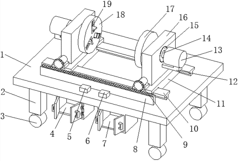
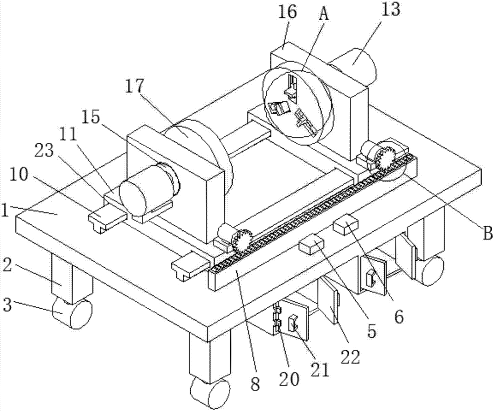
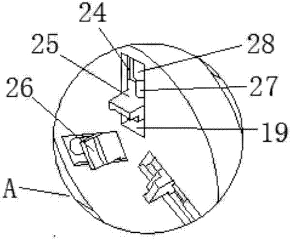
[0021] see Figure 1-4 , the present invention provides a technical solution: a magnetic core clamping device for electronic products, including a base plate 1, the lower surface of the base plate 1 is provided with support legs 2, the number of support legs 2 is four and arranged at equal intervals, the support legs 2 The bottom end of the bottom is provided with roller 3, convenient mobile device, and the bottom surface side of bottom plate 1 is provided wit...


PUM


Abstract

The invention discloses an electronic product magnetic core clamping device. The device comprises a bottom plate, a first control switch and a second control switch are arranged on one side of the upper surface of the bottom plate, two sliding rails are arranged on the upper surface of the bottom plate at equal intervals, sliding plates are clamped at the left ends and the right ends of the two sliding rails in a sliding mode respectively, support plates are arranged on the upper surfaces of the sliding plates, bearings are clamped in through grooves inside the support plates, a first motor isfixed to one side of one support plate through a first motor fixing base, an input end of the first motor is electrically connected with an output end of the first control switch, an output shaft ofthe first motor is connected with a first rotating shaft through a coupling, and the first rotating shaft penetrates through an inner rings of the bearings. According to the electronic product magnetic core clamping device, use is convenient, magnetic cores of different lengths can be clamped, the two ends are fixed and clamped simultaneously, automatic clamping is achieved, the magnetic cores ofdifferent diameters can be clamped, the device is uses widely, subsequent winding work is facilitated, and the working efficiency is improved.

Description

technical field [0001] The invention relates to the technical field of electronic products, in particular to a magnetic core clamping device for electronic products. Background technique [0002] The magnetic core refers to a sintered magnetic metal oxide composed of various iron oxide mixtures. For example, manganese-zinc ferrite and nickel-zinc ferrite are typical magnetic core materials. Manganese-zinc ferrite has The characteristics of high magnetic permeability and high magnetic flux density, and has the characteristics of low loss. Nickel-zinc ferrite has the characteristics of extremely high resistivity and low magnetic permeability of less than a few hundred. Ferrite core It is used in coils and transformers of various electronic devices. With the development of society, electronic products have become an indispensable tool in life. During the production process of electronic products, it is very Importantly, the existing magnetic core clamping devices for electroni...

Claims


Application Information

Patent Timeline
Patent Type & Authority Applications(China)
IPC IPC(8): H01F41/00H01F41/06
CPCH01F41/00H01F41/06
Inventor 吴勇
Owner 珠海美源智科技有限公司
Learn More