Method for preparing free layer of magnetic tunnel junction and method for preparing magnetic tunnel junction

A magnetic tunnel junction and free technology, which is applied in the manufacturing/processing of electromagnetic devices, can solve the problems of poor surface properties of the free layer, achieve the effects of improving TMR value, improving overall performance, and eliminating damage or defects

Active Publication Date: 2018-04-24
CETHIK GRP +1
View PDF8 Cites 5 Cited by
  • Summary
  • Abstract
  • Description
  • Claims
  • Application Information

AI Technical Summary

Problems solved by technology

[0006] The main purpose of the present invention is to provide a method for preparing a free layer of a magnetic tunnel junction and a method for preparing a magnetic tunnel junction, so as to solve the problem of poor surface properties of the free layer using plasma treatment in the prior art

Method used


Image

  • Method for preparing free layer of magnetic tunnel junction and method for preparing magnetic tunnel junction
  • Method for preparing free layer of magnetic tunnel junction and method for preparing magnetic tunnel junction
  • Method for preparing free layer of magnetic tunnel junction and method for preparing magnetic tunnel junction

Examples


preparation example Construction

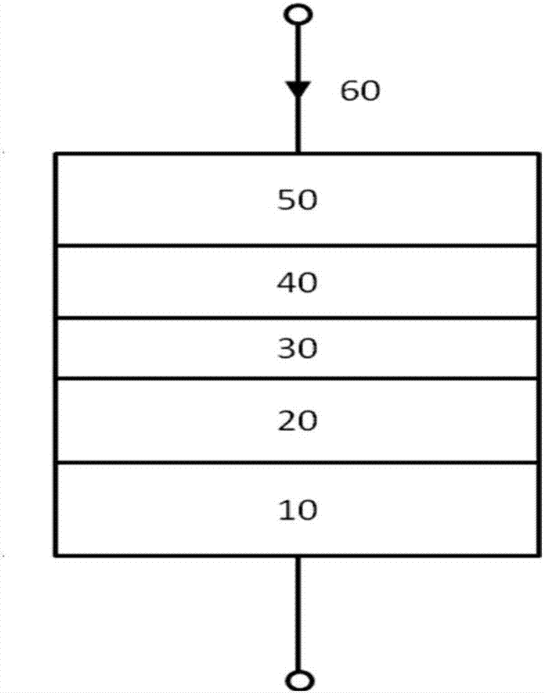
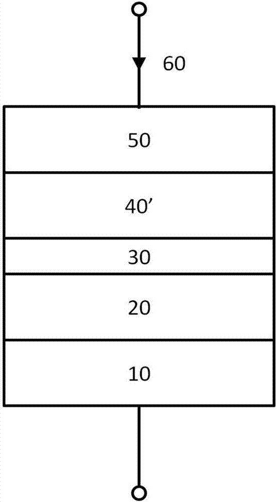
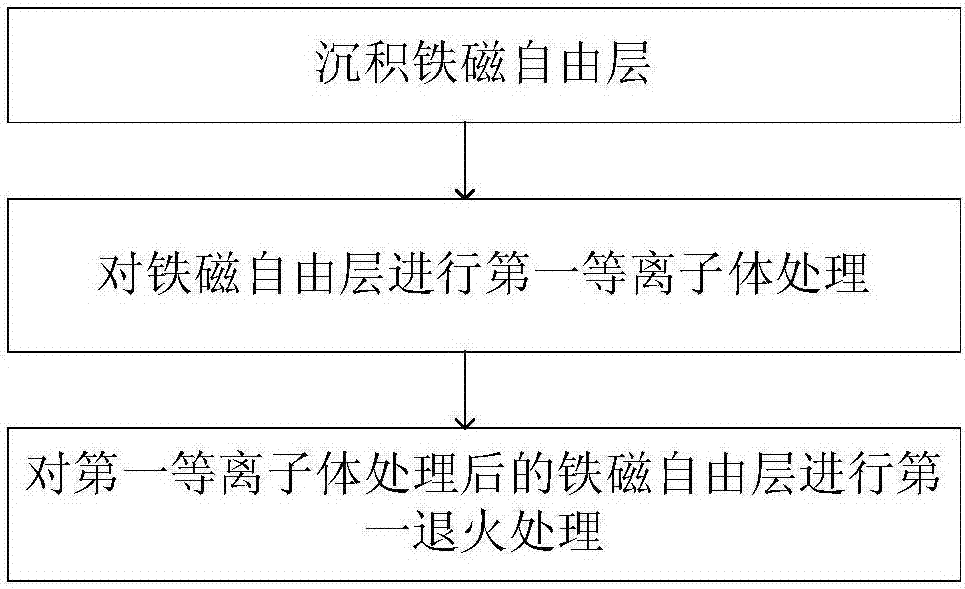
[0053] In the preferred embodiment A, such as figure 2 As shown, the above-mentioned film includes a ferromagnetic free layer 40', and the corresponding preparation method is as image 3 As shown, it includes: depositing a ferromagnetic free layer 40'; performing a first plasma treatment on the ferromagnetic free layer 40'; performing a first annealing treatment on the ferromagnetic free layer 40' after the first plasma treatment.

[0054] The material forming the ferromagnetic free layer 40' in the above embodiment A can be selected from Co, Fe, Ni, CoB, FeB, NiB, CoFe, NiFe, CoNi, CoFeNi, CoFeB, NiFeB, CoNiB, CoFeNiB, FePt, FePd, One or more combinations of CoPt, CoPd, CoFePt, CoFePd, FePtPd, CoPtPd, CoFePtPd. Preferably, the thickness is 0.4 nm to 3 nm. The plasma in the first plasma treatment can be Ar, Kr, Xe, He, N 2 , H 2 , Or O 2 One or more of the other gases are formed. The etching rate of the first plasma treatment is very low, preferably less than 0.02 nm / s. During...

Embodiment approach 1

[0059] Embodiment one: deposit a first ferromagnetic free layer 41; perform a first plasma treatment on the first ferromagnetic free layer 41, and perform a first annealing on the first ferromagnetic free layer 41 after the first plasma treatment Treatment; a non-magnetic metal insertion layer 42 is deposited on the first layer of ferromagnetic free layer 41 after the first annealing treatment; a second layer of ferromagnetic free layer 43 is deposited on the non-magnetic metal insertion layer 42.

Embodiment approach 2

[0060] The second embodiment: depositing a first ferromagnetic free layer 41; depositing a non-magnetic metal insertion layer 42 on the first ferromagnetic free layer 41; performing a first plasma treatment on the non-magnetic metal insertion layer 42 to treat the first plasma The non-magnetic metal insertion layer 42 after the bulk treatment is subjected to a first annealing treatment; a second ferromagnetic free layer 43 is deposited on the non-magnetic metal insertion layer 42 after the first annealing treatment.


PUM

PropertyMeasurementUnit
thicknessaaaaaaaaaa
thicknessaaaaaaaaaa
thicknessaaaaaaaaaa

Abstract

The invention provides a method for preparing a free layer of a magnetic tunnel junction and a method for preparing a magnetic tunnel junction. The method for preparing a free layer of a magnetic tunnel junction includes the steps of setting the films of a free layer through a deposition process, carrying out first plasma treatment on one or more of the films, and carrying out first annealing treatment on the one or more of the films after the first plasma treatment. As in-situ heat treatment is carried out on the one or more films after the first plasma treatment through the first annealing treatment, possible damage or defects caused by the first plasma treatment can be reduced or eliminated, and the surface characteristic of the free layer can be improved. Therefore, the comprehensive performance of a magnetic tunnel junction comprising the free layer can be improved, for example, the TMR value of the magnetic tunnel junction can be improved, and the RA value can be reduced.

Description

Technical field [0001] The invention relates to the field of magnetic random access memory (spin transfer torque magnetic random access memory, STT-MRAM), in particular to a method for preparing a free layer of a magnetic tunnel junction and a method for preparing a magnetic tunnel junction. Background technique [0002] STT-MRAM is a potential and revolutionary general-purpose storage technology that can directly use spin-polarized current to drive the magnetic moment inversion of the nanomagnet to complete information writing. It integrates the high storage density of DRAM, the fast read and write capability of SRAM, the non-volatility and low power consumption of Flash, and high stability. In addition, it has the advantage of unlimited use; compared with traditional MRAM, It has better scalability and lower current for writing information. In particular, it is compatible with more advanced semiconductor processes. [0003] It mainly includes a free layer 40, a reference layer 2...

Claims


Application Information

Patent Timeline
Patent Type & Authority Applications(China)
IPC IPC(8): H01L43/12
CPCH10N50/01
Inventor 刘鲁萍简红蒋信
Owner CETHIK GRP
Why Eureka
Try Eureka