Combined pest capture machine

A compound pest technology, which is applied to the device for capturing or killing insects, application, animal husbandry, etc., can solve the problems of easy accidental injury to natural enemies, low utilization rate, high cost, etc., to avoid accidental injury of natural enemies, adequate pest killing, The effect of attracting insects with high efficiency

Pending Publication Date: 2018-04-27
NANJING AGRI MECHANIZATION INST MIN OF AGRI
View PDF11 Cites 8 Cited by
  • Summary
  • Abstract
  • Description
  • Claims
  • Application Information

AI Technical Summary

Problems solved by technology

As for the physical control scheme, the disadvantage of the insecticidal lamp control method is that the pest killing is not sufficient, the pests lured by the light cannot be completely killed, and it can only work at night, the light wave is not selective, and there is a problem of accidental injury by natural enemies; The prevention and control technology mostly uses yellow sticky boards to achieve the purpose of killing insects by sticking pests. Not only the utilization rate is low, but also the color board needs to be replaced frequently, the cost is high, and it can only be operated during the day; Adsorption hunting will not only cause accidental injury to plants, but also has no selectivity for insects, and it is easy to accidentally injure natural enemies. Moreover, the machine is noisy and the operator's work intensity is relatively high.
Therefore, although the existing non-chemical control methods have a certain control effect on a certain crop pest, they cannot completely replace the chemical control methods on the whole.

Method used


Image

  • Combined pest capture machine
  • Combined pest capture machine
  • Combined pest capture machine

Examples


Embodiment 1

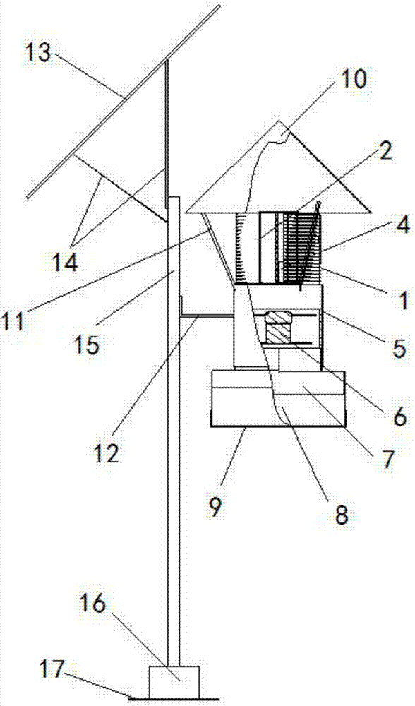
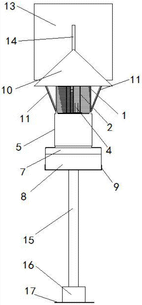
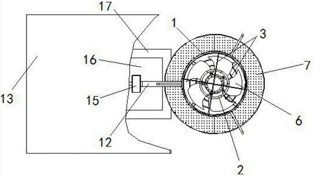
[0031] This embodiment provides a compound pest capture machine, including a power supply system, an automatic control system and a pest catching and killing system, such as figure 1As shown, the pest killing system includes a primary killing mechanism and a secondary killing mechanism that are fixedly connected up and down. The primary killing mechanism includes a high-voltage power grid, and the high-voltage power grid is surrounded by a cylindrical grid enclosure 1. The light trapping device 2, the color plate trapping device and the attractant trapping device 4, the secondary killing mechanism includes a cylindrical casing 5 and a negative pressure fan 6, and the negative pressure fan 6 is installed inside the cylindrical shell 5, The bottom end of the cylindrical grid enclosure 1 is docked with the top end of the cylindrical shell 5, and the axis of the cylindrical grid enclosure 1 coincides with the axis of the cylindrical shell 5, and the bottom of the cylindrical shell ...


PUM


Abstract

The invention discloses a combined pest capture machine. The combined pest capture machine comprises a power supply system, an automatic control system and a pest catching and killing system. The pestcatching and killing system comprises a primary catching and killing mechanism and a secondary catching and killing mechanism, wherein the primary catching and killing mechanism comprises a cylindrical power grid fence, and a light trapping device, a color plate trapping device and an attractant trapping device are arranged in the cylindrical power grid fence; the secondary catching and killing mechanism comprises a cylindrical shell and a negative pressure blower which is installed in the cylindrical shell, the bottom of the cylindrical power grid fence is connected with the top of the cylindrical shell, and a pest collection device is arranged on the bottom of the cylindrical shell. According to the combined pest capture machine, pests are lured by using a color plate in the daytime, pests are trapped and collected by opening the light trapping device in the night, the pests are first killed through the cylindrical power grid fence, secondary catching and killing is conducted by using the negative pressure blower, and the pests obtained after double catching and killing fall into a water storage plate and are thoroughly killed. According to the combined pest capture machine, three catching and killing schemes are utilized, the pests are sufficiently killed, and the pest escape rate is low.

Description

technical field [0001] The invention relates to the technical field of pest capture, in particular to a compound pest capture machine. Background technique [0002] Chemical control has always been the main way of agricultural plant protection. As people pay more and more attention to the problem of food safety, green food has become people's darling. Therefore, green plant protection has gradually become a new topic of agricultural plant protection. [0003] The current non-chemical control methods include biological control and physical control. Biological control mainly includes sexual attractants, natural enemy population control, biological viruses, etc. It still needs to be combined with traditional chemical methods to kill insects, which does not meet the environmental protection requirements of green plant protection. As for the physical control scheme, the disadvantage of the insecticidal lamp control method is that the pest killing is not sufficient, the pests lur...

Claims


Application Information

Patent Timeline
Patent Type & Authority Applications(China)
IPC IPC(8): A01M1/02A01M1/04A01M1/06A01M1/08A01M1/22
CPCA01M1/02A01M1/04A01M1/06A01M1/08A01M1/223
Inventor 肖宏儒韩余宋志禹丁文芹
Owner NANJING AGRI MECHANIZATION INST MIN OF AGRI
Why Eureka
Try Eureka