Movable cloth discharging mechanism with water returning function

An active and functional technology, applied in the direction of liquid/gas/vapor removal with squeeze rollers, processing textile material carriers, and processing textile material equipment configuration, etc., to achieve optimal cost control, avoid slippery pollution and safety issues, and reduce heating effect of time

Pending Publication Date: 2018-04-27
JINJIANG CITY LONGSHENG KNITTING PRINTING & DYEING CO LTD
View PDF0 Cites 0 Cited by
  • Summary
  • Abstract
  • Description
  • Claims
  • Application Information

AI Technical Summary

Problems solved by technology

[0003] In order to overcome the technical defects of the existing technology, the present invention provides a movable fabric outlet mechanism with water return function, which

Method used


Image

  • Movable cloth discharging mechanism with water returning function
  • Movable cloth discharging mechanism with water returning function
  • Movable cloth discharging mechanism with water returning function

Examples


Embodiment 1

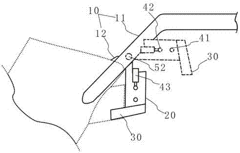
[0024] Such as Figure 1-3 As shown, the present embodiment provides a movable cloth outlet mechanism with water return function, which includes a mounting frame 10 , a cloth guide frame 20 arranged on the mounting frame 10 , a liquid squeezing assembly and a backflow tank 30 . The mounting frame 10 is fixedly mounted on the cloth outlet of the cylinder of the dyeing machine, and includes side frames 11 symmetrically arranged on both lateral sides of the cloth outlet of the cylinder body and horizontal frames 12 horizontally connected between the side frames 11 .

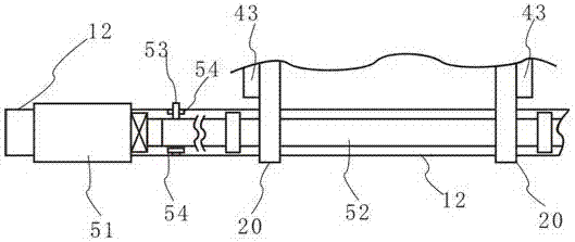
[0025] In this embodiment, the horizontal frame 12 is provided with a rotating motor 51 and a rotating shaft 52, the rotating shaft 52 is arranged on the horizontal frame 12 through a bearing seat and driven to rotate by the rotating motor 51, and the fabric guide frame 20 One end of one end is fixedly connected with the rotating shaft 52, and the specific connection method adopts a conventional connection structure...

Embodiment 2

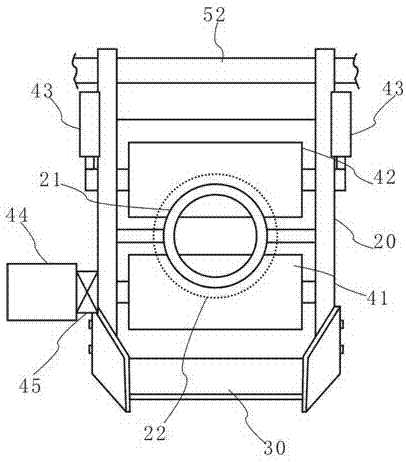
[0032] Such as Figure 4-5As shown, this embodiment provides a movable cloth outlet mechanism with water return function. This embodiment is further improved on the basis of the technical solution of the first embodiment above. The side frame 11 close to the power body of this embodiment A guide groove 13 is provided, and the power body slides and fits with the guide groove 13 through the connecting seat 46, and the guide groove 13 is an arc structure concentrically arranged with the rotating shaft 52, and the guide groove 13 Both ends of the head and tail are provided with a limiting groove 14 that supports and cooperates with the connecting seat 46, and the limiter 60 is movably combined in the limiting groove 14, and one end of the connecting seat 46 is controlled by The limit groove 14 is supported by the limit member 60, so that the structural stability of the power body and the fabric guide frame 20 of this embodiment can be enhanced, and at the same time, it does not af...


PUM


Abstract

The invention specifically discloses a movable cloth outlet mechanism with water return function, which includes a mounting frame, a cloth guide frame, a liquid rolling assembly, and a return flow tank arranged on the mounting frame. The side frames on both sides of the mouth and the horizontal frame connected horizontally between the side frames are provided with a rotating motor, a rotating shaft driven by the rotating motor and set on the horizontal frame through a bearing seat, and a Proximity switch for the forward and reverse angle of the rotating shaft, one end of the cloth guide frame is fixedly connected with the rotating shaft, the liquid squeezing assembly is arranged on the cloth guiding frame, and the return groove is arranged on the other side of the cloth guiding frame away from the rotating shaft one end. The invention can greatly reduce the amount of liquid brought out by the fabric, avoid slippery pollution and safety problems caused by the remaining liquid dripping on the workshop floor, and can avoid or reduce the impact caused by the fabric guide frame rotating up and down with the cylinder of the dyeing machine. harm.

Description

technical field [0001] The invention relates to the technical field of dyeing and finishing equipment, in particular to a movable cloth outlet mechanism with water return function, which is installed at the cloth inlet and outlet of the dyeing machine vat. Background technique [0002] Overflow dyeing machines are used to dye fabrics. After the dyeing is finished, the fabric in the machine cylinder is taken out to proceed to the next process. But in the process of taking out, a large amount of dye liquor will be taken out of the machine cylinder along with the fabric and flow to the ground. Like this, not only wasted a large amount of reusable dye liquor (apply existing technology, the dye liquor after dyeing can be reused), and seriously polluted workshop environment, and affected the health of operator to a certain extent. Contents of the invention [0003] In order to overcome the technical defects of the existing technology, the present invention provides a movable f...

Claims


Application Information

Patent Timeline
IPC IPC(8): D06B15/02D06B23/04D06B23/20
CPCD06B15/02D06B23/04D06B23/20
Inventor 刘志军段亮黄燕珠朱学勋
Owner JINJIANG CITY LONGSHENG KNITTING PRINTING & DYEING CO LTD
Why Eureka
Try Eureka