Jet flow groove cooling structure capable of improving cooling efficiency of stator leading edge nearby end wall

A technology of cooling efficiency and cooling structure, applied in the direction of stators, engine components, machines/engines, etc., can solve problems such as inability to obtain cooling protection, achieve the effects of eliminating high heat load areas, reducing separation, and improving service life

Inactive Publication Date: 2018-04-27
XI AN JIAOTONG UNIV
View PDF3 Cites 7 Cited by
  • Summary
  • Abstract
  • Description
  • Claims
  • Application Information

AI Technical Summary

Problems solved by technology

The traditional cooling structure can improve the cooling efficiency of the end wall near the leading edge of the stator b

Method used


Image

  • Jet flow groove cooling structure capable of improving cooling efficiency of stator leading edge nearby end wall
  • Jet flow groove cooling structure capable of improving cooling efficiency of stator leading edge nearby end wall
  • Jet flow groove cooling structure capable of improving cooling efficiency of stator leading edge nearby end wall

Examples


Embodiment Construction

[0032] The present invention will be further described in detail below in conjunction with the accompanying drawings and technical principles. Concrete structure of the present invention sees appendix Figure 3-8 , the design idea is as follows:

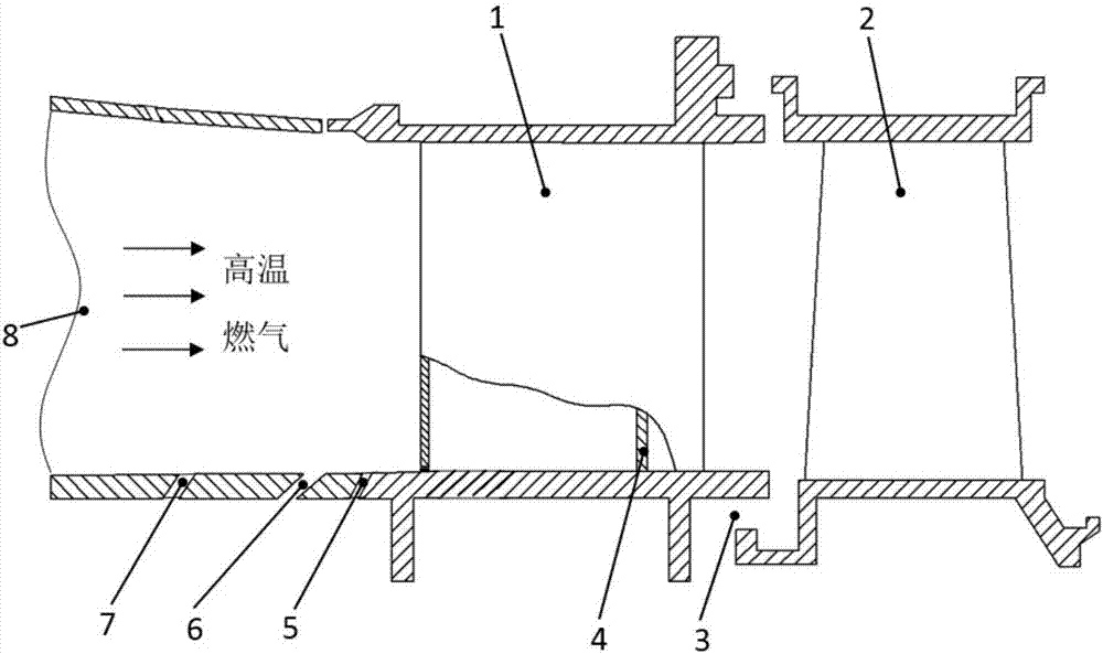
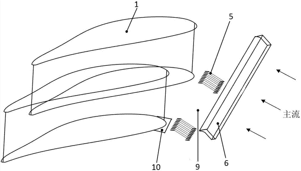
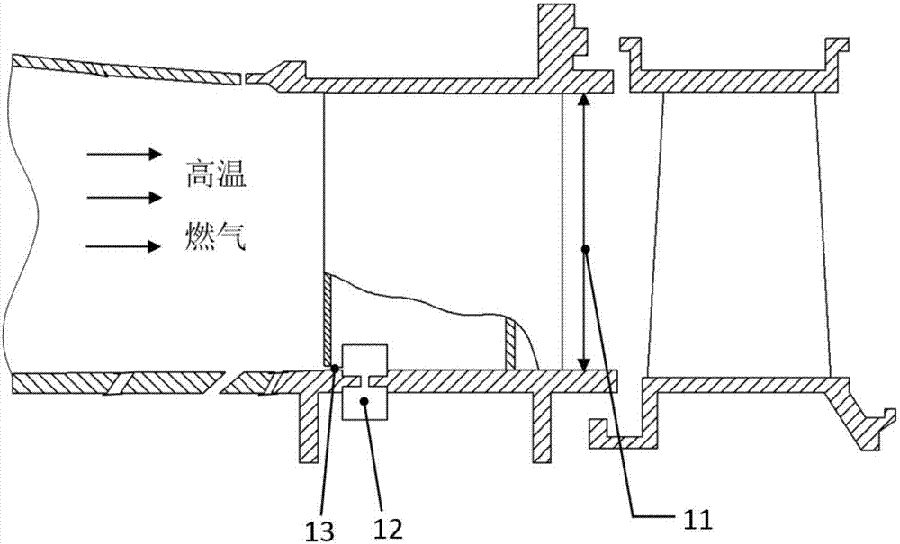
[0033] see image 3 and Figure 4 The jet groove cooling structure provided by the present invention has the cooling efficiency of the end wall near the leading edge of the vane, including the cooling jet chamber 12 and the jet groove 13 installed at the root of the gas turbine vane 1; wherein the cooling jet chamber 12 is along the The direction of the cooling flow runs through the root of the gas turbine vane 1, and the jet slot 13 runs through the rib 4 inside the vane from the combustion chamber 8 along the intake direction of the high-temperature gas and communicates with the outlet of the cooling jet chamber 12. Wherein, the gas turbine vane 1 is connected to the gas turbine rotor blade 2 through a rim seal 3 .

[0034] and ...


PUM

PropertyMeasurementUnit
Diameteraaaaaaaaaa

Abstract

The invention discloses a jet flow groove cooling structure capable of improving the cooling efficiency of a stator leading edge nearby end wall. The jet flow groove cooling structure comprises a cooling jet flow cavity (12) and a jet flow groove (13) which are installed at the root of a gas turbine stator (1). The cooling jet flow cavity (12) penetrates through the root of the gas turbine stator(1) in the direction of cooling flows, and the jet flow groove (13) penetrates through a fin (4) in the stator from a combustion chamber (8) in the gas intake direction of high-temperature gas, and communicates with an outlet of the cooling jet flow cavity (12). In the working process, cooling jet flows led in from a gas compressor pass through the cooling jet flow cavity (12) to enter the jet flow groove (13), and finally the cooling jet flows enter a main flow area of a blade cascade channel from a jet flow groove outlet (14) in the root of the stator. An even cooling gas film is formed nearby the end wall nearby the stator leading edge by the cooling jet flows under the effects of a leading edge corner vertex and a horseshoe vortex, and the cooling gas film is tightly attached to the surface of end wall to flow towards the upstream, so that sufficient cooling protection is conducted on the end wall nearby the leading edge.

Description

technical field [0001] The invention relates to a cooling structure, in particular to a jet groove cooling structure which improves the cooling efficiency of the end wall near the front edge of the vane. Background technique [0002] As the main device for energy conversion and utilization, gas turbines are widely used in the fields of power generation, aviation, chemical industry and mechanical power. With the rapid development of social economy, the sharp increase of energy demand and the increasingly prominent environmental problems put forward stricter requirements for the design of gas turbines. So far, in order to solve the problems of energy shortage and environmental pollution, on the one hand, the thermal efficiency of the gas turbine can be significantly improved by increasing the inlet gas temperature to reduce CO 2 emissions; on the other hand, by improving the design of the combustion chamber, the gas temperature distribution is uniform to reduce the gas temper...

Claims


Application Information

Patent Timeline
IPC IPC(8): F01D9/02F01D25/12
CPCF01D9/02F01D25/12F05D2240/12F05D2240/121F05D2260/202
Inventor 李军杜昆李志刚
Owner XI AN JIAOTONG UNIV
Why Eureka
Try Eureka