
Sintering furnace with silicon wafer capable of being dried in suspended manner

A technology of sintering furnace and drying furnace, which is applied in the direction of drying, dryer, furnace, etc., can solve the problems of low drying efficiency and high energy consumption, and achieve the purpose of improving drying efficiency, ensuring drying effect, and drying air flow Optimized effect

Active Publication Date: 2018-04-27
LESHAN TOPRAYCELL
View PDF3 Cites 2 Cited by
  • Summary
  • Abstract
  • Description
  • Claims
  • Application Information

AI Technical Summary

Problems solved by technology

[0006] Because the hot air rises upward, the drying air in the drying furnace area in the prior art mainly provides the power to form the air flow through the exhaust fan, and the air flow reverses, resulting in high energy consumption and low drying efficiency.

Method used


Image

  • Sintering furnace with silicon wafer capable of being dried in suspended manner
  • Sintering furnace with silicon wafer capable of being dried in suspended manner
  • Sintering furnace with silicon wafer capable of being dried in suspended manner

Examples


Embodiment Construction

[0034] The present invention will be further described below in conjunction with the accompanying drawings and embodiments.

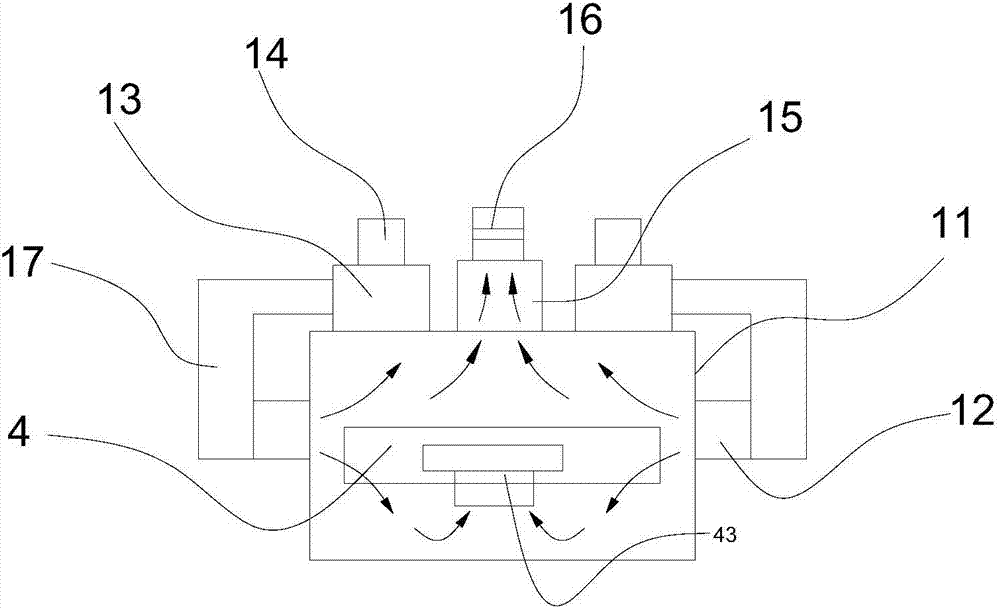
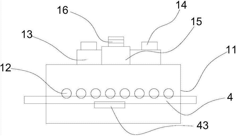
[0035] Such as Figure 1 to Figure 3 As shown, the sintering furnace for drying silicon wafers in the air according to the present invention includes a drying furnace area 1, a sintering furnace area 2, a cooling furnace area 3 and a conveying device 4, and the conveying device 4 runs through the drying furnace area in sequence 1. Sintering furnace area 2, cooling furnace area 3;

[0036] The conveying device 4 located in the drying furnace area 1 is provided with an air injection device 43; the conveying device 4 includes two driving rollers 41 and a supporting seat before and after; the driving roller 41 is supported by a supporting seat 48, and the driving roller 41 A conveyor belt 42 is wound on it, and the conveyor belt 42 is a conveyor net; the support base 48 is provided with a drive device 5 for driving the drive roller 41 to rotate;

[0037] ...


PUM


Abstract

The invention discloses a sintering furnace, capable of facilitating flowing of drying gas flow in a drying furnace area, with a silicon wafer capable of being dried in a suspended manner. The sintering furnace with the silicon wafer capable of being dried in the suspended manner comprises the drying furnace area, a sintering furnace area, a cooling furnace area and a conveying device, and a gas spraying device is arranged below the portion, located in the drying furnace area, of the conveying device; the drying furnace area comprises a furnace body; a gas extracting device is arranged on thetop of a drying furnace cavity; gas inflow pipes are arranged on the side wall of the furnace body, and the gas inflow pipes are uniformly distributed on the side face of the furnace body in the length direction; the gas inflow pipes are located above the upper surface of the conveying device at the gas inflow port position in the drying furnace cavity, and the other portion is located below the upper surface of the conveying device; and an air heating air blowing device is arranged on the top of the furnace body, and an air outlet of the air heating air blowing device is communicated with thegas inflow pipes. By adopting the sintering furnace with the silicon wafer capable of being dried in the suspended manner, the drying gas flow can be optimized, and the drying efficiency is improved.

Description

technical field [0001] The invention relates to the field of sintering of solar cells, in particular to a sintering furnace capable of hanging and drying silicon wafers. Background technique [0002] It is well known that in the entire production process of solar cells, the three processes of diffusion, coating and sintering are the most important. Currently, solar cells adopt a co-firing process that only requires one sintering; at the same time, the ohmic contact of the upper and lower electrodes is formed. [0003] The sintering process of solar cells in the prior art mainly includes three steps of drying and preheating, sintering and cooling; the equipment for sintering solar cells generally adopts a sintering furnace, and the sintering furnace includes a drying zone, a sintering zone and a cooling zone. [0004] Sintering is a crucial step to make the crystalline silicon substrate truly have the function of photoelectric conversion. Therefore, the performance of the si...

Claims


Application Information

Patent Timeline
IPC IPC(8): F27B9/02F27B9/20F26B21/00
CPCF26B21/001F27B9/028F27B9/20
Inventor 陈五奎刘强任超
Owner LESHAN TOPRAYCELL
Learn More