Novel heat exchanger for carbon fiber production line

A production line and carbon fiber technology, applied in the field of heat exchange mechanisms for carbon fiber production lines, can solve the problems of cumbersome production of heat exchange tubes, large capital investment, and prolonging the continuous operation time of the production line, so as to prolong the continuous operation time, improve economic benefits, and reduce replacement. The effect of the thermal dead zone

Pending Publication Date: 2018-04-27
ZHEJIANG JINGGONG SCI & TECH
View PDF0 Cites 0 Cited by
  • Summary
  • Abstract
  • Description
  • Claims
  • Application Information

AI Technical Summary

Problems solved by technology

The existing solution is to make one heat exchanger and one spare to prolong the continuous running time of

Method used


Image

  • Novel heat exchanger for carbon fiber production line
  • Novel heat exchanger for carbon fiber production line
  • Novel heat exchanger for carbon fiber production line

Examples


Example Embodiment

[0017] The present invention will be further described below in conjunction with the drawings and specific embodiments.

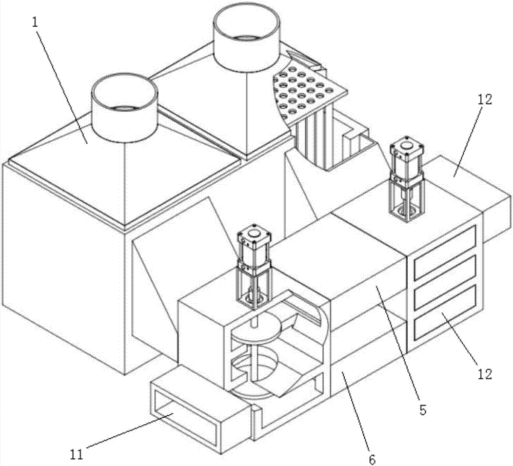
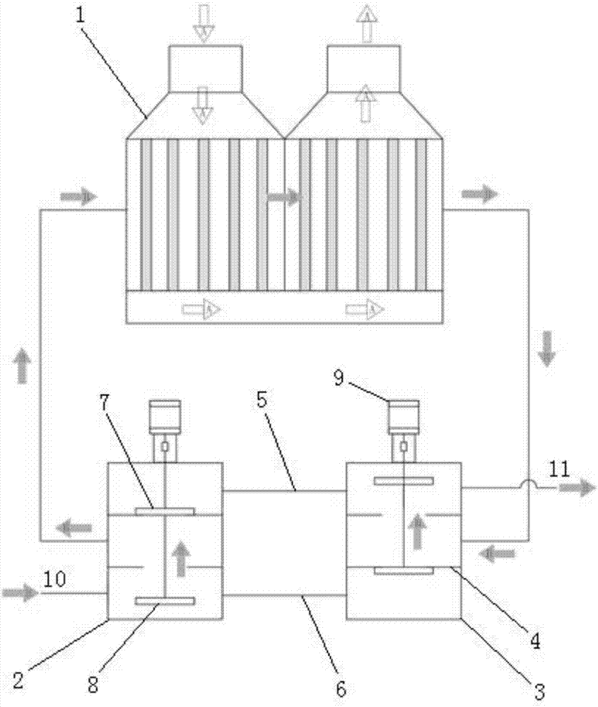
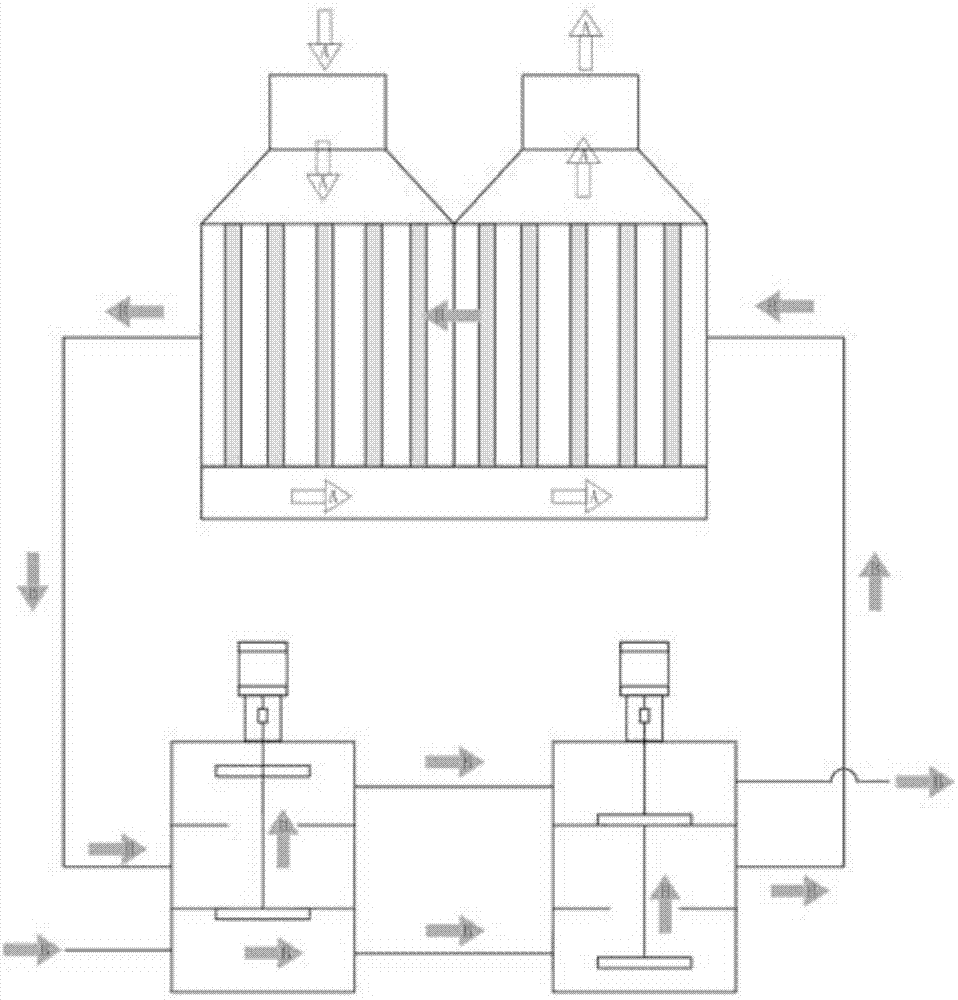
[0018] As shown in the figure, a heat exchange mechanism for a carbon fiber production line includes a heat exchanger 1, a first reversing chamber 2, a second reversing chamber 3, the first reversing chamber 2, and the second reversing chamber 3 pass After the two-layer partition 4 is set, it is divided into an upper space, a middle space and a lower space. The middle space of the first reversing chamber 2 and the second reversing chamber 3 are respectively connected to the heat exchanger 1 through a connecting channel. The upper space between the chamber 2 and the second reversing chamber 3 is communicated through the upper waste passage 5, and the lower space between the first reversing chamber 2 and the second reversing chamber 3 is communicated through the lower waste passage 6 in the partition 4 Open through holes, in the first reversing chamber 2 and the...


PUM


Abstract

The invention relates to the field of heat exchangers, in particular to a heat exchanging mechanism for a carbon fiber production line. The heat exchanging mechanism for the carbon fiber production line comprises a heat exchanger, a first reversing chamber and a second reversing chamber. The first reversing chamber and the second reversing chamber are each internally provided with two partitions to from an upper space, a middle space and a lower space. The middle space of the first reversing chamber and the middle space of the second reversing chamber communicate with the heat exchanger through connection channels. The upper space of the first reversing chamber communicates with the upper space of the second reversing chamber through an upper waste channel. The lower space of the first reversing chamber communicates with the lower space of the second reversing chamber through a lower waste channel. The partitions are provided with through holes. The first reversing chamber and the second reversing chamber are internally provided with an upper reversing valve element and a lower reversing valve element which can synchronously ascend or descend. The shape of the upper reversing valveelement and the shape of the lower reversing valve element coordinate with the through holes. By means of the technical scheme, the continuous running time of equipment is prolonged, and therefore the economic benefits of the carbon fiber production line are improved.

Description

technical field [0001] The invention relates to the field of heat exchangers, in particular to a heat exchange mechanism for a carbon fiber production line. Background technique [0002] The carbon fiber industry has developed rapidly in recent years, but the cost of carbon fiber manufacturing remains high, resulting in slow progress in the industrialization and commercialization of carbon fiber. In order to reduce the cost in the carbon fiber manufacturing process, carbon fiber equipment is developing in the direction of large-scale and large-scale. At the same time, a larger scale means more energy consumption, which means that more energy will be used in the carbon fiber manufacturing process. in the drain. How to improve the heat energy utilization rate of the waste gas produced in the pre-oxidation furnace, low carbon furnace and high carbon furnace in the production line and how to improve the online production time are more and more paid attention to in the carbon fi...

Claims


Application Information

Patent Timeline
IPC IPC(8): F28G13/00F28G15/00
CPCF28G13/00F28G15/00
Inventor 傅春锋傅建根朱吉元王永法孙兴祥卫国军金越顺
Owner ZHEJIANG JINGGONG SCI & TECH
Why Eureka
Try Eureka