
Efficient encoder

A high-efficiency coding and encoder technology, applied in the field of electronic devices, can solve the problem of insufficient coding efficiency of the encoder, and achieve the effect of improving the transmission signal effect and prolonging the corrosion resistance.

Inactive Publication Date: 2018-04-27
HUAIAN SHENGYU ELECTRONICS
View PDF0 Cites 0 Cited by
  • Summary
  • Abstract
  • Description
  • Claims
  • Application Information

AI Technical Summary

Problems solved by technology

[0005] The purpose of the present invention is to provide a high-efficiency encoder to solve the problem that the encoding efficiency of the current encoder is not high enough in the above-mentioned background technology

Method used


Image

  • Efficient encoder

Examples


Embodiment Construction

[0012] The following will clearly and completely describe the technical solutions in the embodiments of the present invention with reference to the accompanying drawings in the embodiments of the present invention. Obviously, the described embodiments are only some, not all, embodiments of the present invention. Based on the embodiments of the present invention, all other embodiments obtained by persons of ordinary skill in the art without making creative efforts belong to the protection scope of the present invention.

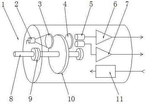
[0013] The present invention provides such figure 1 A high-efficiency encoder shown includes an encoder body 1, a light-emitting diode 2, a prism 3, a fixed grating 4, a photosensitive tube 5, a signal element 6, a signal element 2 7, a rotating shaft 8, a bearing 9, and a grating plate 10 and a power supply 11, the encoder body 1 is provided with a rotating shaft 8; a bearing 9 is fixed on the rotating shaft 8; a grating plate 10 is fixed on the rotating shaf...


PUM


Abstract

The invention discloses a high-efficiency encoder, which includes an encoder body, a light-emitting diode, a prism, a fixed grating, a photosensitive tube, a signal element 1, a signal element 2, a rotating shaft, a bearing, a grating plate and a power supply. A rotating shaft is provided; a bearing is fixed on the rotating shaft; a grating plate is fixed on the rotating shaft; a prism is arranged at one end of the grating plate; a light-emitting diode is arranged at one end of the prism; There is a fixed grating; one end of the fixed grating is provided with a photosensitive tube; one end of the photosensitive tube is provided with a signal element one; the signal element one is provided with a signal element two; the signal element two is provided with a power supply. The beneficial effect of the invention is that by arranging the signal element 1 and the signal element 2 made of silver material, the signal transmission effect of the encoder is greatly improved, and the service life of the encoder is also prolonged.

Description

technical field [0001] The invention belongs to the technical field of electronic devices, and in particular relates to a high-efficiency encoder. Background technique [0002] An encoder is a device that compiles and converts signals or data into signal forms that can be used for communication, transmission and storage. The encoder converts angular displacement or linear displacement into an electrical signal, the former is called a code disc, and the latter is called a yardstick. According to the readout method, the encoder can be divided into two types: contact type and non-contact type; according to the working principle, the encoder can be divided into two types: incremental type and absolute type. The incremental encoder converts the displacement into a periodic electrical signal, and then converts the electrical signal into a counting pulse, and uses the number of pulses to represent the magnitude of the displacement. Each position of the absolute encoder correspond...

Claims


Application Information

Patent Timeline
IPC IPC(8): G01D5/26
CPCG01D5/26
Inventor 宗启军
Owner HUAIAN SHENGYU ELECTRONICS
Features
  • Generate Ideas
  • Intellectual Property
  • Life Sciences
  • Materials
  • Tech Scout
  • Unparalleled Data Quality
  • Higher Quality Content
  • 60% Fewer Hallucinations
Learn More