Circular array modal domain orientation estimation method based on space sparse constraint

A technology of sparse constraints and orientation estimation, which is applied to systems for determining direction or offset, and direction finders using ultrasonic/sonic/infrasonic waves. It can solve problems such as low accuracy, low algorithm execution efficiency, and long prediction time. Achieve good position estimation performance, reduce computational complexity, and improve resolution

Active Publication Date: 2018-04-27
HEILONGJIANG INST OF TECH
View PDF9 Cites 9 Cited by
  • Summary
  • Abstract
  • Description
  • Claims
  • Application Information

AI Technical Summary

Problems solved by technology

[0005] The purpose of the present invention is to solve the problem that the existing modal domain orientation estimation method needs a large number of multi-snapshot sampling data to construct the covariance matrix, and needs to invert the covariance matrix or decompose

Method used


Image

  • Circular array modal domain orientation estimation method based on space sparse constraint
  • Circular array modal domain orientation estimation method based on space sparse constraint
  • Circular array modal domain orientation estimation method based on space sparse constraint

Examples


specific Embodiment approach 1

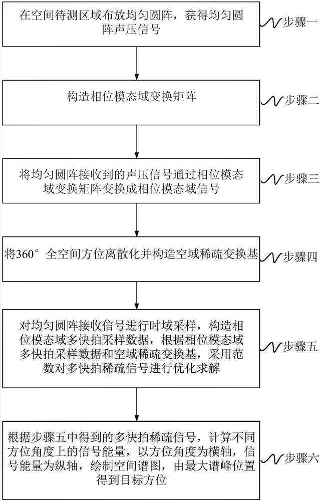
[0017] Specific implementation mode 1: The circular array modal domain orientation estimation method based on spatial sparse constraints in this implementation mode, such as figure 1 shown, including:

[0018] Step 1. Arrange a uniform circular array in the area to be measured in space to obtain a uniform circular array sound pressure signal P(t);

[0019] Step 2. Construct the phase modal domain transformation matrix T;

[0020] Step 3, transforming the sound pressure signal P(t) received by the uniform circular array into a phase modal domain signal X(t) through the phase modal domain transformation matrix T;

[0021] Step 4. Discretize the 360° full spatial orientation, and construct the spatial sparse transformation base

[0022] Step 5: Sampling the received signal of the uniform circular array in the time domain, constructing multi-snapshot sampling data X in the phase modal domain, according to the multi-snapshot sampling data X in the phase modal domain and the spa...

specific Embodiment approach 2

[0024] Specific implementation mode two: the difference between this implementation mode and specific implementation mode one is that step one is specifically:

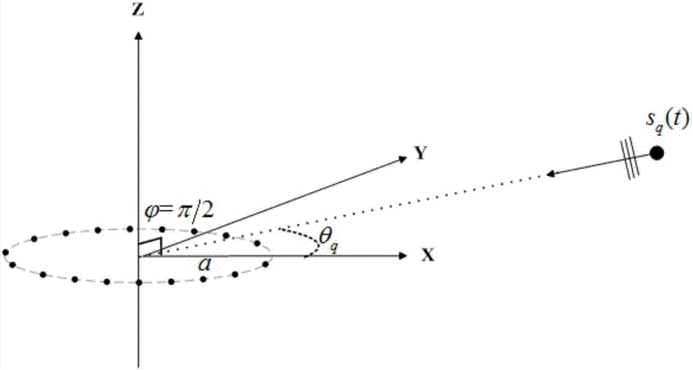
[0025] Place an N-element uniform circular array with a radius a in the horizontal x-y plane, and assume that there are Q narrowband signals s in the space q (t)(q=1,...,Q) and located on the same plane as the uniform circular array, the incident angles are θ q (q=1,...,Q), such as figure 2 shown.

[0026] Then the sound pressure signal received by the nth array element can be expressed as:

[0027]

[0028] in, is the wave number, f is the signal frequency, c is the speed of sound; M is the maximum number of phase modes that can be excited by the circular array, and the value is the smallest integer greater than ka; is the imaginary unit; J m (·) is an m-order Bessel function; e is a mathematical constant.

[0029] Further, the sound pressure signal P(t) received by the uniform circular array can be expre...

specific Embodiment approach 3

[0040] Specific implementation mode three: the difference between this implementation mode and specific implementation mode one or two is that step two is specifically:

[0041] The transfer function diagonal matrix B is inverted, then multiplied by the complex conjugate transpose of the spatial Fourier transform matrix F, and finally divided by the number of array elements N, the phase modal domain transformation matrix T is constructed, namely

[0042]

[0043] in,(·) -1 Indicates the matrix inversion operation, ( ) H Represents the complex conjugate transpose of a matrix.

[0044] Other steps and parameters are the same as those in Embodiment 1 or Embodiment 2.


PUM


Abstract

The invention relates to the hydroacoustic engineering technology field, particularly relates to a circular array modal domain orientation estimation method based on space sparse constraint and aims to solve problems that multi-shot sampling data is required to construct a covariance matrix, inversion or characteristic value decomposition is required for the covariance matrix and algorithm execution efficiency is relatively low existing in a modal domain orientation estimation method in the prior art. The method comprises steps that a uniform circular array sound pressure signal is acquired; aphase modal domain transformation matrix is constructed; a sound pressure signal received by a uniform circular array is transformed into a phase modal domain signal through a phase modal domain transformation matrix; the 360-DEG full space orientation is discretized, and a space domain sparse transformation base is further constructed; time domain sampling of a uniform circular array reception signal is carried out to construct multi-shot sampling data in a phase modal domain, and optimization and solution of multi-shot sparse signals are carried out through utilizing the l1 norm; signal energy in different orientation angles is calculated, a spatial spectrum is drawn, and the target orientation is acquired through the maximum peak position. The method is advantaged in that the method issuitable for signal estimation of the hydroacoustic engineering.

Description

technical field [0001] The invention relates to the technical field of underwater acoustic engineering, in particular to a circular array modal domain orientation estimation method based on spatial sparse constraints. Background technique [0002] In the field of array signal processing, space target positioning technology has attracted the attention of many researchers and is widely used in the fields of national economy and national defense construction such as radar, sonar, and medical imaging. In the past few decades, a variety of array structures with different functions have emerged one after another, the most simple and practical of which is the Uniform Linear Array (ULA). Based on the uniform line array, many classic orientation estimation algorithms (for example, the maximum entropy spectrum method (Maximum Entropy: ME), the maximum likelihood method (Maximum Likelihood: ML), and the characteristic subspace method, etc.) have also been born. However, the uniform li...

Claims


Application Information

Patent Timeline
IPC IPC(8): G01S3/802
CPCG01S3/802
Inventor 宋海岩秦进平唐弢邹海英佟宁宁刘海成
Owner HEILONGJIANG INST OF TECH
Why Eureka
Try Eureka