
Liquid-state metal battery

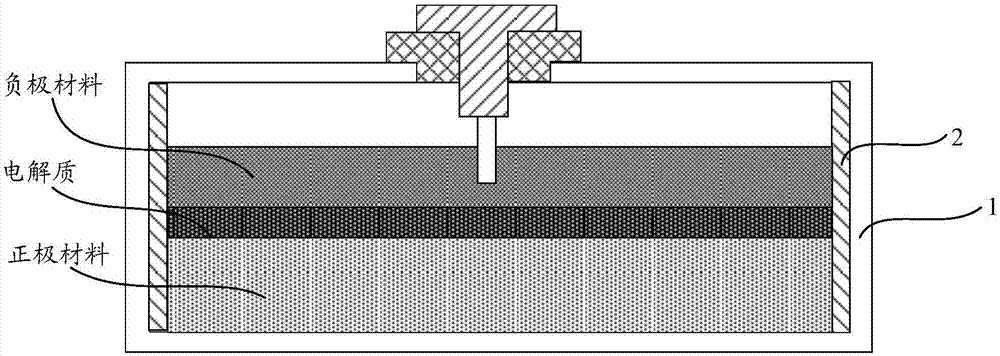
A liquid metal battery, metal battery technology, applied in secondary batteries, battery pack parts, battery boxes/jackets, etc., can solve problems such as complex processing technology, leakage of positive and negative electrode materials and molten electrolytic salt, and different thermal expansion coefficients

Active Publication Date: 2018-04-27
ENN SCI & TECH DEV
View PDF5 Cites 2 Cited by
  • Summary
  • Abstract
  • Description
  • Claims
  • Application Information

AI Technical Summary

Problems solved by technology

[0005] However, when the insulating ceramic layer is coated on the inner wall of the metal battery case to prevent the short circuit of the positive and negative electrodes, the processing technology is complicated and the cost is high, and the thermal expansion coefficient of the insulating ceramic layer is different from that of the metal battery case. The cracking and falling off of the insulating ceramic layer are easy to occur; when the insulating ceramic tube is installed inside the metal battery case to prevent the short circuit of the positive and negative electrodes, the bottom of the insulating ceramic tube and the bottom of the metal battery case need to be coated with high temperature resistant insulating seal If cracks occur in some parts of the glue, the leakage of positive and negative electrode materials and electrolytic salts will easily occur, resulting in battery performance degradation or even failure. Moreover, as the molten positive and negative electrode materials and electrolytic salts corrode the metal battery case, It is easy to cause leakage of positive and negative electrode materials and molten electrolytic salt, which can easily cause fire and explosion

Method used


Image

  • Liquid-state metal battery
  • Liquid-state metal battery
  • Liquid-state metal battery

Examples


Embodiment Construction

[0027] The following will clearly and completely describe the technical solutions in the embodiments of the present invention with reference to the accompanying drawings in the embodiments of the present invention. Obviously, the described embodiments are only some, not all, embodiments of the present invention. Based on the embodiments of the present invention, all other embodiments obtained by persons of ordinary skill in the art without making creative efforts belong to the protection scope of the present invention.

[0028] In describing the present invention, it is to be understood that the terms "center", "upper", "lower", "front", "rear", "left", "right", "vertical", "horizontal", The orientations or positional relationships indicated by "top", "bottom", "inner", "outer", etc. are based on the orientations or positional relationships shown in the drawings, and are only for the convenience of describing the present invention and simplifying the description, rather than in...


PUM


Abstract

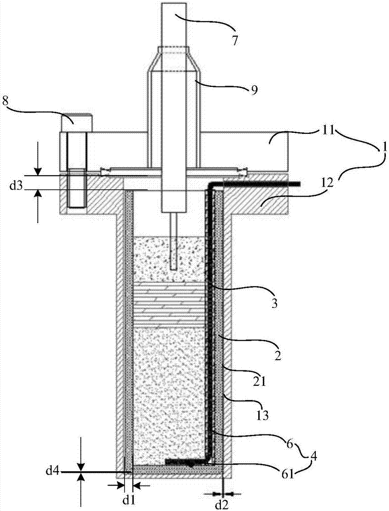
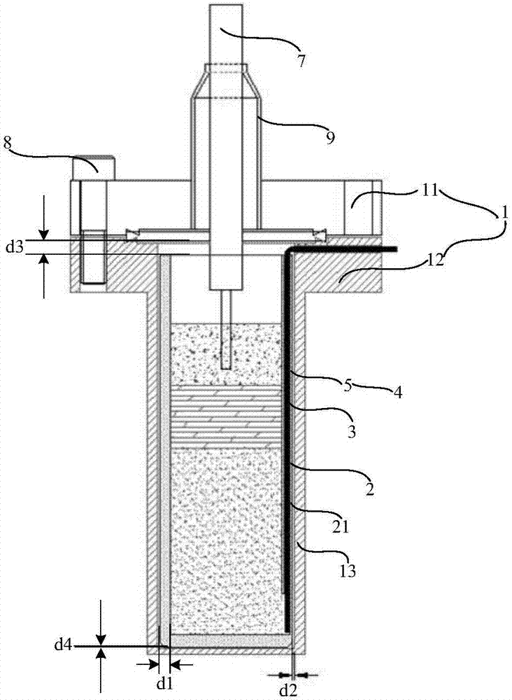
The invention relates to the technical field of a liquid-state metal battery, in particular to a liquid-state metal battery. By the liquid-state metal battery, the reliability of a sealing effect is improved as well as a positive electrode is effectively guided, leakage of a positive electrode material, a negative electrode material and an electrolysis salt is prevented, the lifetime of the battery is prolonged, and the safety of the battery is improved. The liquid-state metal battery provided by the invention comprises a metal battery shell and an insulation crucible, wherein the insulation crucible is arranged in the metal battery shell and is of a cylindrical structure which is closed in lower end and opening in upper end, a positive electrode material, an electrolyte and a negative electrode material are sequentially arranged in the insulation crucible from bottom to top, the positive electrode material is electrically connected with the metal battery shell via a positive leading-out line, at least one part of positive leading-out line is immersed in the positive electrode material and is electrically connected with the positive electrode material, the positive leading-out lineis led out of the opening of the upper end of the insulation crucible and is electrically connected with the metal battery shell, and an insulation protection device is arranged at an outer side of apart, corresponding to the electrolyte and the negative electrode material, of the positive leading-out line.

Description

technical field [0001] The invention relates to the technical field of liquid metal batteries, in particular to a liquid metal battery. Background technique [0002] A liquid metal battery is a high-temperature battery in which all parts of a liquid metal battery exist in liquid form during operation: a low-density liquid metal negative electrode, a molten salt electrolyte, and a high-density liquid metal positive electrode. Due to the different densities and incompatibility between each other, the three parts are naturally divided into three layers. When discharging, the negative electrode metal loses electrons and does work through the external circuit. After the negative electrode metal is ionized, it migrates to the positive electrode through the molten salt and alloys with the positive electrode metal. When charging, the battery performs the reverse process. Through the above-mentioned alloying and dealloying process, the liquid metal battery can complete the storage...

Claims


Application Information

Patent Timeline
IPC IPC(8): H01M10/38H01M10/39H01M2/02H01M2/08H01M2/22H01M2/34H01M50/119H01M50/186H01M50/528H01M50/59
CPCH01M10/38H01M10/399H01M50/138H01M50/183H01M50/528H01M50/572Y02E60/10Y02P70/50
Inventor 王宇宋韵洋刘敏胜
Owner ENN SCI & TECH DEV
Learn More