Switch reluctance motor

A technology of switched reluctance motors and motor rotors, which is applied in the direction of electric components, electrical components, electromechanical devices, etc., and can solve problems such as the greater influence of the degree of synchronization between the rotor and the main shaft, and achieve the effects of saving raw materials, reducing collisions, and improving accuracy

Active Publication Date: 2018-04-27
CHUANGYUAN YIDE TIANJIN GRP CO LTD
View PDF14 Cites 1 Cited by
  • Summary
  • Abstract
  • Description
  • Claims
  • Application Information

AI Technical Summary

Problems solved by technology

[0005] However, when the rotor made of this type of rotor sheet is connected to the main shaft of the motor, it is necessary to set a keyway corresponding to the keyway hole on the main shaft, and connect the rotor and the main shaft through a key. The degree of synchronization is greatly affected by the fit of the key and the keyway in the assembly

Method used


Image

  • Switch reluctance motor
  • Switch reluctance motor
  • Switch reluctance motor

Examples


Embodiment 1

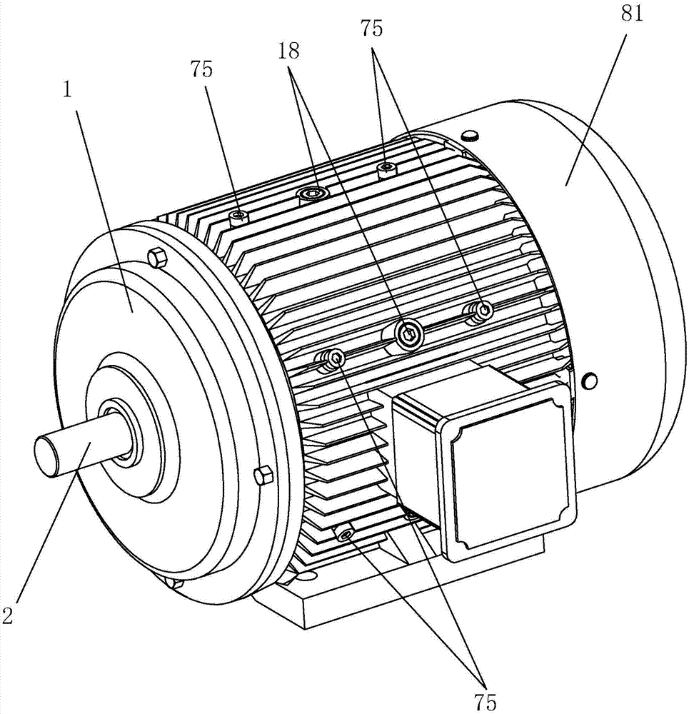
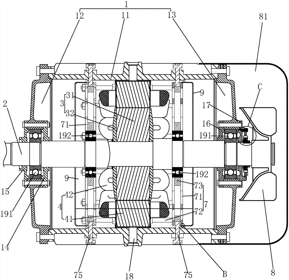
[0052] Embodiment 1: as figure 1 and figure 2 As shown, it includes a casing 1, a main shaft 2 rotatably connected to the casing 1, a motor rotor 3 fixed on the main shaft 2, a motor stator 4 fixed in the casing 1, and a reluctance type for detecting the position of the motor rotor 3. Rotary transformer 5, support frame 7 and soundproof cover 9.

[0053] The casing 1 includes a machine base 11 with two ends open, a front end cover 12 flanged to one end of the machine base 11 , and a rear end cover 13 flanged to the other end of the machine base 11 . The centers of the front end cover 12 and the rear end cover 13 respectively have bearing holes, and the first bearings 191 supporting the rotation of the main shaft 2 and located at both ends of the main shaft 2 are provided in the bearing holes.

[0054] The front end cover 12 is fixedly connected with a front bearing inner end cover 14 and a front bearing outer end cover 15 which lock the axial position of the first bearing 1...

Embodiment 2

[0077] Embodiment 2: The difference with Embodiment 1 is that, as Figure 19 As shown, each rotor key table 313 is respectively facing the gap between the salient poles 312 of two adjacent motor rotors; that is, the mid-vertical line of the rotor key table 313 close to the shaft center end surface of the shaft hole 314 is located between two adjacent motor rotors. The distance between the salient poles 312 and to the salient poles 312 of the two motor rotors is equal.

Embodiment 3

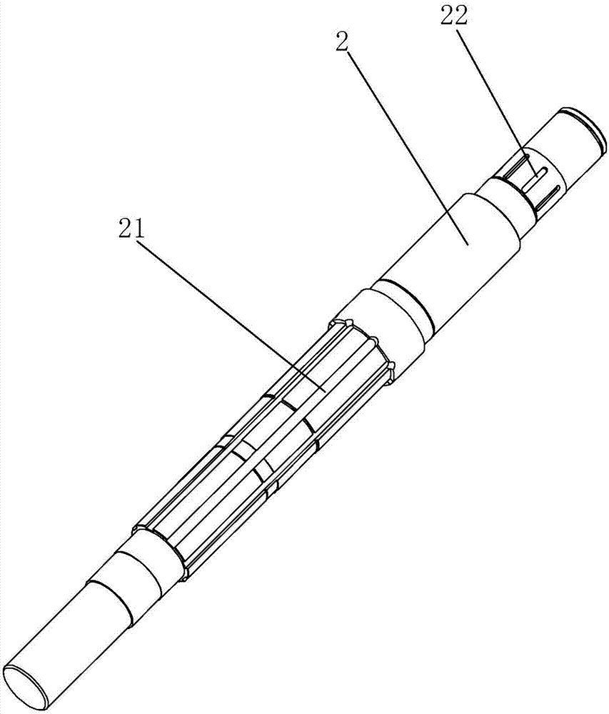
[0078] Embodiment 3: The difference with Embodiment 1 is that, as Figure 20 As shown, the resolver key table 522 is aligned with the rotor salient pole 312 , that is, the second key slot 62 is aligned with the rotor key slot 21 .


PUM


Abstract

The invention discloses a switch reluctance motor. The switch reluctance motor is technically characterized in that the switch reluctance motor comprises a casing, a main shaft rotationally connectedwith the casing, a motor rotor which is fixedly connected with the main shaft, a motor stator which is fixedly connected with the inside casing, and a position detector. The motor rotor comprises a rotor piece and end plates arranged on both ends of the motor rotor. A number of motor rotor salient poles are evenly arranged on the rotor piece. A shaft hole is arranged in the center of the rotor piece. Rotor key tables are integrally fixedly arranged on the circumference of the shaft hole. The number of the rotor key tables is consistent with the number of the motor rotor salient poles, and the rotor key tables are evenly distributed on the circumferential surface of the shaft hole. Rotor key slots matching the rotor key tables are arranged on the main shaft, which can reduce the degree ofinfluence of the rotor on the rotation synchronism of the main shaft.

Description

technical field [0001] The invention relates to a motor, in particular to a switched reluctance motor. Background technique [0002] Switched reluctance motor is a new type of speed regulation motor. The speed regulation system has the advantages of both DC and AC speed regulation systems. It is the latest generation of stepless speed regulation system following the frequency conversion speed regulation system and brushless DC motor speed regulation system. It has simple and firm structure, wide speed regulation range, excellent speed regulation performance, high efficiency in the whole speed regulation range, and high system reliability. [0003] The whole system mainly consists of four parts: switched reluctance motor, power converter, controller and position detector. The switched reluctance motor is a variable reluctance motor with double salient poles, and the salient poles of the stator and rotor are made of laminated ordinary silicon steel sheets. The rotor has neit...

Claims


Application Information

Patent Timeline
IPC IPC(8): H02K1/24H02K1/28H02K1/18H02K5/24H02K29/08
CPCH02K1/18H02K1/24H02K1/28H02K5/24H02K29/08
Inventor 申杨孙德海张伟
Owner CHUANGYUAN YIDE TIANJIN GRP CO LTD
Why Eureka
Try Eureka