
Embedded electromagnetic liquid cooling retarder with speed increaser

A technology of eddy current retarder and retarder, applied in the direction of electric brake/clutch, asynchronous induction clutch/brake, electrical components, etc., which can solve the problems of low braking power density, reducing the mass and volume of the retarder body, etc. , to achieve convenient control, reduce rotor weight, and good heat dissipation effect

Inactive Publication Date: 2018-04-27
BEIJING UNIV OF TECH
View PDF7 Cites 4 Cited by
  • Summary
  • Abstract
  • Description
  • Claims
  • Application Information

AI Technical Summary

Problems solved by technology

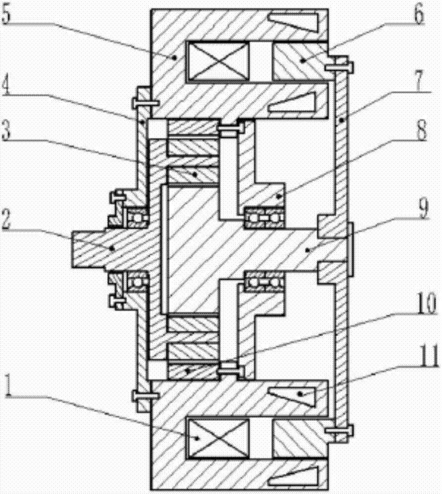
[0005] The invention overcomes the low braking power density of the existing eddy current retarder, and proposes a built-in electromagnetic liquid cooling retarder with a speed increaser on the basis of the structure of the eddy current retarder, through the planetary gear mechanism Increase the speed of the retarder rotor, according to the braking power formula of the eddy current retarder, P=2π*k*n*T, increase the speed n of the input shaft by k times through the planetary gear mechanism (k takes a value between 2- 3), under the condition that the braking power P remains unchanged, the braking torque T of the retarder can be reduced to T / k, thereby greatly reducing the mass volume of the retarder body, effectively ensuring The braking performance of the car at medium and low speeds, and the structure is relatively simple and easy to control

Method used


Image

  • Embedded electromagnetic liquid cooling retarder with speed increaser
  • Embedded electromagnetic liquid cooling retarder with speed increaser

Examples


Embodiment Construction

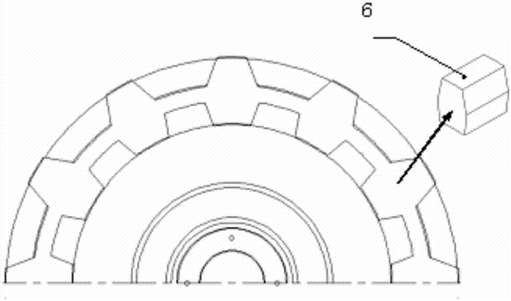
[0018] Specific embodiments of the present invention will be further described below in conjunction with the accompanying drawings. Such as figure 1 and figure 2 As shown, the rotor of the retarder in the embodiment of the present invention is connected with the sun gear, and connected with the output shaft of the automobile transmission or the output half shaft of the differential through the planetary gear mechanism. In the retarder stator groove. The ring gear 10 in the planetary gear is connected with the retarder stator 5 by bolts and fixed together on the vehicle frame. The controller controls the magnitude of the braking torque by adjusting the excitation current in the excitation coil 1 of the retarder according to the signal of the Hall sensor or the driver's instruction. A gap of 1-2 millimeters is maintained between the addendum arc of the rotor magnetically conducting tooth 6 and the arc of the inner surface of the stator 5 outer layer, and the arc of the tooth...


PUM


Abstract

An embedded electromagnetic liquid cooling retarder with a speed increaser belongs to the automobile auxiliary braking field. The retarder comprises an eddy current retarder portion and a planetary gear mechanism portion. The eddy current retarder portion comprises a retarder stator, a retarder rotor and an excitation coil. An axial section of the retarder stator is a C-shaped structure. A water channel is arranged in the stator and an external layer surface is provided with a water inlet and a water outlet. The excitation coil is wound into a shape and then is directly and fixedly arranged inthe stator. The rotor is divided into a magnetic conductive tooth portion and a connection portion. A magnetic conductive tooth is embedded between internal and external layers of the stator. A rotorflange is connected to a sun gear of a planetary gear mechanism. The retarder increases a rotation speed of the retarder rotor through the planetary gear mechanism and a speed n of an input shaft isincreased by k times (the k is between 2 and 3). Under the condition that braking power P is not changed, a braking torque T of the retarder can be reduced to T / k so that a massic volume of a retarderbody can be greatly reduced. The structure is simple, a rotational inertia of the rotor is small, a water cooling effect is good and braking safety of an automobile is improved.

Description

technical field [0001] The invention relates to a built-in electromagnetic liquid-cooled retarder with a speed increaser, which is equipped with a planetary gear mechanism, which can amplify the rotational speed of the output shaft of the automobile transmission or the output shaft of the differential, thereby improving its manufacturing efficiency. The dynamic power density effectively ensures the eddy current braking performance of the retarder at the middle and low speed of the automobile, and belongs to the field of automobile auxiliary braking. Background technique [0002] Automobile retarder is a non-contact auxiliary braking device, which can better solve the problem of severe degradation of braking performance caused by continuous braking of automobiles, and at the same time share the braking load of the braking system, greatly The safety, economy and comfort of vehicle driving are mentioned. [0003] At present, when the car is running at medium and low speeds, th...

Claims


Application Information

Patent Timeline
IPC IPC(8): H02K49/04H02K9/19
CPCH02K49/046H02K9/19
Inventor 李德胜郭文光纪克红田金山高志伟
Owner BEIJING UNIV OF TECH
Learn More