Efficient lathe scrap recycling device

A recycling device and high-efficiency technology, applied in the field of lathes, can solve the problems of reducing the work efficiency of workers, many operation steps, slow recycling, etc., and achieve the effect of improving the work efficiency of workers

Inactive Publication Date: 2018-05-01
佘峰
View PDF4 Cites 5 Cited by
  • Summary
  • Abstract
  • Description
  • Claims
  • Application Information

AI Technical Summary

Problems solved by technology

[0005] Aiming at the deficiencies of the prior art, the present invention provides a high-efficiency recovery device for lathe waste chips, which solves the shortcomings of the existing iron chip recovery devices

Method used


Image

  • Efficient lathe scrap recycling device
  • Efficient lathe scrap recycling device

Examples


Example Embodiment

[0020] The technical solutions in the embodiments of the present invention will be clearly and completely described below with reference to the accompanying drawings in the embodiments of the present invention. Obviously, the described embodiments are only a part of the embodiments of the present invention, but not all of the embodiments. Based on the embodiments of the present invention, all other embodiments obtained by those of ordinary skill in the art without creative efforts shall fall within the protection scope of the present invention.
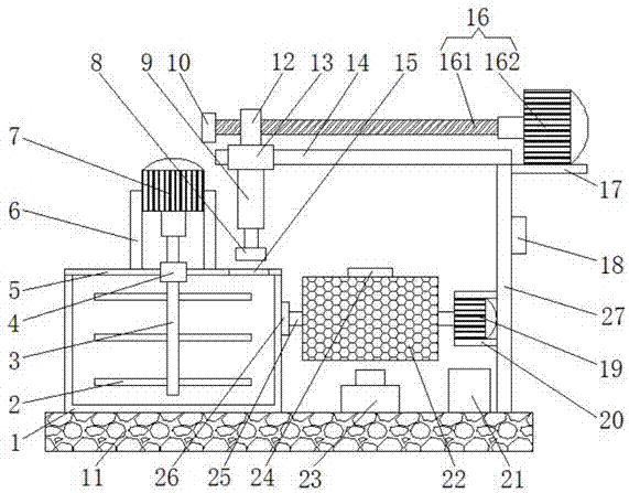
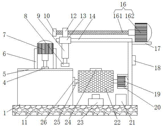
[0021] like Figure 1-2 As shown, the present invention provides a technical solution: an efficient recovery device for lathe waste, comprising a bottom plate 11, the upper surface of the bottom plate 11 is fixedly connected with a casing 1, and the upper surface of the casing 1 is overlapped with a first cover plate 5 , by setting the first cover plate 5, so that when the iron filings need to be cleaned, the worker can pick up the fi...


PUM


Abstract

The invention discloses an efficient lathe scrap recycling device which comprises a bottom plate. The upper surface of the bottom plate is fixedly connected with a shell. The upper surface of the shell is in lap joint with a first cover plate. The upper surface of the first cover plate is connected with a first bearing in a clamping mode. A first rotary shaft is sleeved with the first bearing. Thetop end of the first rotary shaft is fixedly connected with an output shaft of a first motor. According to the efficient lathe scrap recycling device, a control panel, the first motor, a second motor, a third motor, a net barrel, the first bearing, the first rotary shaft, an air blower and an electric push rod are arranged, the first rotary shaft rotates and drives stirring rods to rotate by controlling the first motor to work, the stirring rods drive scrap and water in the shell to rotate, meanwhile, the air blower is controlled to work and blow air towards the net barrel so that water spotson iron scrap can be blown away, thus, the workload is reduced, operation steps are reduced, the recycling speed is increased, therefore, the working efficiency of workers is improved, and meanwhile,machining of factories to parts is not delayed.

Description

technical field [0001] The invention relates to the technical field of lathes, in particular to a high-efficiency recycling device for lathe waste. Background technique [0002] A lathe is a machine tool that mainly uses a turning tool to turn a rotating workpiece. It mainly consists of spindle box, exchange gear box, feed box, slide box, tool holder, tailstock, feed rod, lead screw, bed, bed foot and cooling device and other components. Drills, reamers, reamers, taps, dies and knurling tools can also be used for corresponding processing on the lathe. [0003] The lathe will produce a lot of iron filings when processing parts. In order to save costs, many manufacturers will recycle the iron filings for reprocessing. The time for recycling also reduces the work efficiency of workers and delays the processing of parts by manufacturers. Contents of the invention [0004] (1) Solved technical problems [0005] Aiming at the deficiencies of the prior art, the present invent...

Claims


Application Information

Patent Timeline
IPC IPC(8): B08B3/10B03C1/02B09B3/00B09B5/00F26B11/18F26B21/00
CPCB03C1/02B08B3/102B09B3/00B09B5/00F26B11/182F26B21/004
Inventor 佘峰
Owner 佘峰
Why Eureka
Try Eureka