Cover plate positioning pin

A technology of positioning pins and cover plates, which is applied to bolts, metal processing equipment, forming tools, etc., to achieve the effects of reducing processing precision, simple material selection, and simple structure

Inactive Publication Date: 2018-05-01
江苏今道高新技术发展有限公司
4 Cites 0 Cited by

AI-Extracted Technical Summary

Problems solved by technology

[0002] The turret punch press uses the stamping die to perform punching processing and shallow drawing on the plate. The upper die is installed in the installation hole of the upper turret, and the lower die is installed in the corresponding installation hole of the lower turret mold holder. To prevent the lower die from jumping out of the die holder during the stamping process, ...

Method used

[0018] Further, the two ends of the positioning pin 01 are provided with chamfers 0102 to facilitate the installat...

Abstract

The invention discloses a cover plate positioning pin. The cover plate positioning pin comprises a positioning pin body and a top wire, the positioning pin body is perpendicularly fixed to a die supporting seat, and the top wire is movably arranged on the die supporting seat and is perpendicular to the positioning pin body. According to the novel cover plate positioning pin, the structure is simple, material obtaining is easy, machining is easy, meanwhile, the machining precision of a cover plate pin hole is reduced, and quick positioning of a cover plate is achieved.

Application Domain

Shaping toolsBolts

Technology Topic

EngineeringMechanical engineering

Image

  • Cover plate positioning pin

Examples

  • Experimental program(1)

Example Embodiment

[0013] The technical solutions in the embodiments of the present invention will be described in detail below with reference to the drawings in the embodiments of the present invention. Obviously, the described embodiments are only a part of the embodiments of the present invention, rather than all the embodiments. Based on the embodiments of the present invention, all other embodiments obtained by those of ordinary skill in the art without creative work shall fall within the protection scope of the present invention.
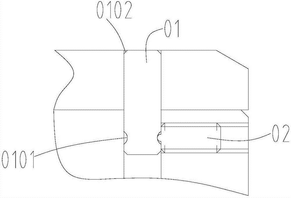
[0014] Participate figure 1 As shown, the cover plate positioning pin in the present invention includes positioning pin 01 and top wire 02, positioning pin 01 is vertically fixed to the mold holder base, top wire 02 is movably arranged on the mold holder base, top wire 02 is perpendicular to positioning pin 01, The cover plate positioning pin of the invention has simple structure, simple material extraction and easy processing.
[0015] Further, the positioning pin 01 is provided with an arc-shaped ring groove 0101 at the end of the mold bracket. After loosening the top wire 02, the positioning pin 01 can shake slightly. At this time, it is simple to install the cover. When the cover is installed, the top is tightly fixed. Wire 02, so that the positioning pin 01 is completely fixed, that is, the positioning of the cover is completed.
[0016] Further, the top wire 02 is a steel ball top wire, and the steel ball in front of the top wire 02 is matched with the arc-shaped ring groove 0101 to realize the fixation of the positioning pin 01.
[0017] Furthermore, the steel ball of the top wire 02 is pressed against the arc-shaped ring groove 0101, and the steel ball is clamped into the arc-shaped ring groove 0101 when the top wire 02 is tightened to ensure that the positioning pin 01 is completely fixed.
[0018] Further, both ends of the positioning pin 01 are provided with chamfers 0102 to facilitate the installation of the positioning pin 01, and at the same time play a guiding role when the positioning pin 01 is installed in the cover plate.
[0019] The positioning pin of the invention has simple structure, simple material extraction and easy processing. At the same time, it reduces the accuracy of cover plate pin hole processing and realizes rapid positioning of the cover plate. After loosening the top wire, the positioning pin can shake slightly. At this time, it is simple to install the cover plate. After the cover plate is installed, tighten the top wire so that the positioning pin is completely fixed, that is, the cover plate is positioned.
[0020] It should be noted that in this article, relational terms such as first and second are only used to distinguish one entity or operation from another entity or operation, and do not necessarily require or imply one of these entities or operations. There is any such actual relationship or order between. Moreover, the terms "include", "include" or any other variants thereof are intended to cover non-exclusive inclusion, so that a process, method, article or device including a series of elements not only includes those elements, but also includes those that are not explicitly listed Other elements of, or also include elements inherent to this process, method, article or equipment. If there are no more restrictions, the element defined by the sentence "including a..." does not exclude the existence of other same elements in the process, method, article, or equipment including the element.
[0021] The above are only specific implementations of this application. It should be pointed out that for those of ordinary skill in the art, without departing from the principles of this application, several improvements and modifications can be made. These improvements and modifications are also Should be regarded as the scope of protection of this application.

PUM

no PUM

Description & Claims & Application Information

We can also present the details of the Description, Claims and Application information to help users get a comprehensive understanding of the technical details of the patent, such as background art, summary of invention, brief description of drawings, description of embodiments, and other original content. On the other hand, users can also determine the specific scope of protection of the technology through the list of claims; as well as understand the changes in the life cycle of the technology with the presentation of the patent timeline. Login to view more.

Similar technology patents

Biometric identification apparatus

InactiveUS20080037001A1perform accurately and rapidlysimple structure
Owner:HITACHI MEDIA ELECTORONICS CO LTD

Fuel cell

ActiveUS20070207372A1simple structuremaintain durability
Owner:HONDA MOTOR CO LTD

Isolation implant in abdominal aorta external and internal iliac artery cavity

Owner:SECOND MILITARY MEDICAL UNIV OF THE PEOPLES LIBERATION ARMY

Classification and recommendation of technical efficacy words

  • Simple structure
  • Simple

Sharing system for air-conditioning coat

InactiveCN107440179ASimple structureeasy to wear
Owner:QINGDAO HAIER AIR CONDITIONER GENERAL CORP LTD

Emergency parachuting device and method for multiple-rotor unmanned aerial vehicle

InactiveCN103895870Aavoid aircraft crashSimple structure
Owner:SOUTH CHINA AGRI UNIV +1

Quick pipe connector

Owner:YANG RICHARD

Automatic washing and dewatering combined device of rotary type mop

InactiveCN102370447Areduce volumeSimple structure
Owner:上海祥美网络科技有限公司 +1

Magnetic clasp device for clothing accessories

ActiveUS20120216374A1simple
Owner:MANUELLO GERARLD

Hand-held setting tool

ActiveUS20050121487A1simpleeasily produce
Owner:HILTI AG

Simplified GNSS receiver with improved precision in a perturbated environment

InactiveUS20180180741A1simple
Owner:CENT NAT DETUD SPATIALES C N E S

Electric meter tote

InactiveUS20060032783A1simpledurable in construction
Owner:DETROIT EDISON CO

Sternal closure and ribs approximator devices

ActiveUS20150127004A1simple
Owner:PATIL AJAY K
Why Eureka
Try Eureka