A continuous sand mixer and sand mixing process

A sand mixer and sand mixing technology are applied in the direction of manufacturing tools, metal processing equipment, and machinery for cleaning/processing casting materials, etc., which can solve problems such as low efficiency, lack of environmental monitoring, and inability to achieve continuous sand mixing. To achieve the effect of improving performance and improving efficiency

Active Publication Date: 2021-03-19
SUZHOU MINGZHI TECH
View PDF10 Cites 1 Cited by
  • Summary
  • Abstract
  • Description
  • Claims
  • Application Information

AI Technical Summary

Problems solved by technology

However, this method can only complete the sand mixing at one time, and the next sand mixing can only be carried out after the stirred sand is taken out. Therefore, this method is intermittent and cannot achieve continuous sand mixing, which is inefficient.
In order to achieve continuous sand mixing, there is a sand mixing method using a continuous sand mixer in the prior art. After the raw sand enters the sand bucket, it passes through the sand mixing tank, and the raw sand and auxiliary materials move while mixing in the sand mixing tank. It can realize continuous sand mixing, mainly used for sand mixing of self-hardening sand, but for sand with high requirements on the external environment during the mixing process, for example, it is necessary to ensure that the temperature is within a narrow range during the mixing process, and the sand mixing tank needs to ensure A certain humidity prevents the sand from dehydration and hardening, especially for the sand mixing of inorganic sand and cold core sand. This method lacks monitoring of the environment and cannot guarantee the performance of the sand.

Method used


Image

  • A continuous sand mixer and sand mixing process
  • A continuous sand mixer and sand mixing process

Examples


Embodiment Construction

[0029] The technical solutions of the present invention will be further described below in conjunction with the accompanying drawings and through specific implementation methods.

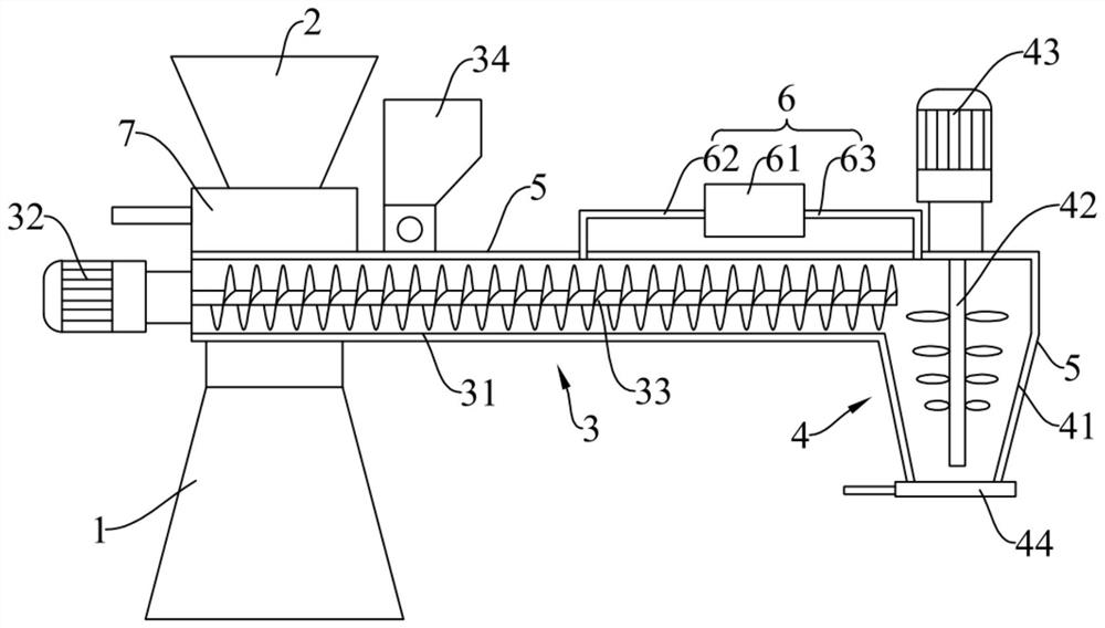
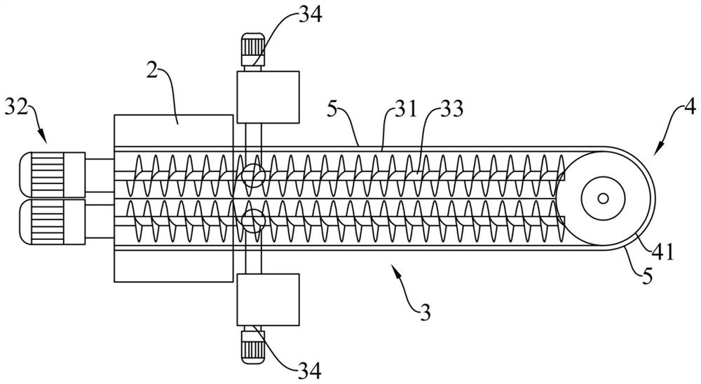
[0030] Such as figure 1 and figure 2 As shown, the continuous sand mixer includes a machine base 1, a mixing device connected to the machine base 1, and a sand feeding hopper 2 connected to the mixing device. The mixing device includes a conveying sand mixing mechanism 3 and a final mixing mechanism 4. The sand is fed into the sand hopper 2, and the outlet of the sand feeding hopper 2 is connected with the inlet of the conveying sand mixing mechanism 3. 4, the final mixing mechanism 4 is used for final mixing of sand. The continuous sand mixing is realized by conveying the sand mixing mechanism 3 and the final mixing mechanism 4, which improves the sand mixing efficiency and ensures the continuous progress of the sand mixing action.

[0031] The conveying sand mixing mechanism 3 includes a sand ...


PUM


Abstract

Disclosed is a sand mixer, comprising a machine base (1), a mixing device connected to the machine base, and a sand feeding hopper (2) and a water spray device (6) connected to the mixing device, wherein the mixing device comprises a sand conveying and mixing mechanism (3) and a final mixing mechanism (4), a first end of the sand conveying and mixing mechanism is connected to the sand feeding hopper, and a second end of the sand conveying and mixing mechanism is connected to the final mixing mechanism; the outside of both the sand conveying and mixing mechanism and the final mixing mechanism is sheathed with a temperature control cylinder (5), a gap for introducing a temperature control medium is provided between the temperature control cylinder and the sand conveying and mixing mechanism and between the temperature control cylinder and the final mixing mechanism; and the water spray device is respectively in communication with the sand conveying and mixing mechanism and the final mixing mechanism. A sand mixing process is further comprised. The sand mixer realises continuous sand mixing, and effectively controls the temperature of sand and the internal humidity, thereby improving the sand mixing efficiency and the performance of mixed sand.

Description

technical field [0001] The invention relates to the technical field of sand mixing equipment, in particular to a continuous sand mixing machine and a sand mixing process. Background technique [0002] The sand used for the sand mold of casting products needs to add auxiliary materials such as binders and accelerators to the original sand to meet its strength and other performance indicators. In the process of adding auxiliary materials, the sand and auxiliary materials need to be fully mixed. [0003] The commonly used sand mixing method is intermittent sand mixing. Pour the sand and auxiliary materials into the container together, and drive the stirring shaft to rotate through the motor to stir the mixture. After a certain period of time, the stirring is completed. However, this method can only complete the sand mixing at one time, and the next sand mixing can only be carried out after the stirred sand is taken out. Therefore, this method is intermittent and cannot achieve ...

Claims


Application Information

Patent Timeline
Patent Type & Authority Patents(China)
IPC IPC(8): B22C5/04B22C5/08
CPCB22C5/0413B22C5/0472B22C5/08
Inventor 徐磊磊陆高春
Owner SUZHOU MINGZHI TECH
Why Eureka
Try Eureka