Feeding mechanism of universal joints

A technology of feeding mechanism and universal joint, which is applied in the direction of conveyors, conveyor objects, rotary conveyors, etc., can solve the problems of raw material collision, affecting the processing efficiency of universal joints, vibration, etc., and achieve the effect of reducing workload

Pending Publication Date: 2018-05-01
PINGHU PINYAO MACHINERY AUTOMATION CO LTD
View PDF0 Cites 1 Cited by
  • Summary
  • Abstract
  • Description
  • Claims
  • Application Information

AI Technical Summary

Problems solved by technology

However, due to the limitation of the axial size, the deflection angle is required to be relatively large. A single universal joint cannot make the instantaneous angular velocity of the output shaft and the shaft input shaft equal, which is easy to cause vibration, aggravate the damage of components, and generate a lot of noise. Therefore, a wide variety of constant velocity universal joints are widely used.
[0005] At the same time, in various pneumatic and manual tools, it is often necessary to use joints to connect and transmit force. The above-mentioned joints are generally connected to the sleeve, and the sleeve is then connected to the force arm. When the external force is applied to the force arm When it is on, the force is transmitted to the connecting piece with the joint through the sleeve and the joint, and finally the joint exerts force on the fastener, thereby fastening the fastener to the connected object. At the same time, some pneumatic tools and During the use of hand tools, the environment is more complicated. For example, in the process of car maintenance, the space left for operators and maintenance tools will be limited. Therefore, for the convenience of maintenance and use, people have developed universal joints that can change the direction according to needs.
[0006] In the prior art, the feeding of the spherical universal joint usually adopts a mobile feeding method. Before placing the material on the feeder, it is usually necessary to prevent the material in a specific arrangement, so that it is convenient for the subsequent process. Feed the materials, which requires the operator to place the raw materials reasonably, which increases the workload of the operators; at the same time, due to the collision between the raw materials during the feeding process, it will cause certain changes in the placement of the raw materials , affecting the feeding efficiency of the feeder, thus affecting the processing efficiency of the universal joint

Method used


Image

  • Feeding mechanism of universal joints
  • Feeding mechanism of universal joints
  • Feeding mechanism of universal joints

Examples


Embodiment Construction

[0024] Embodiments of the present invention will be described in detail below in conjunction with the accompanying drawings.

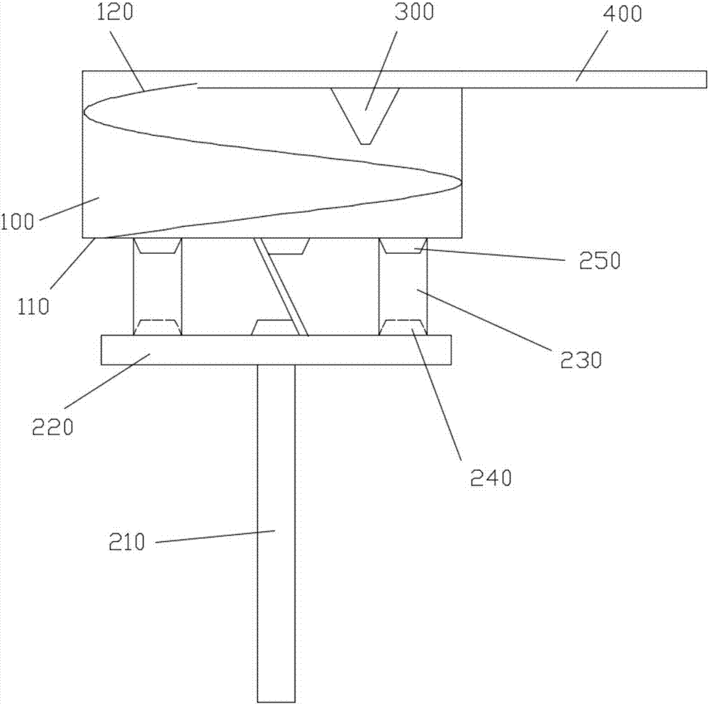
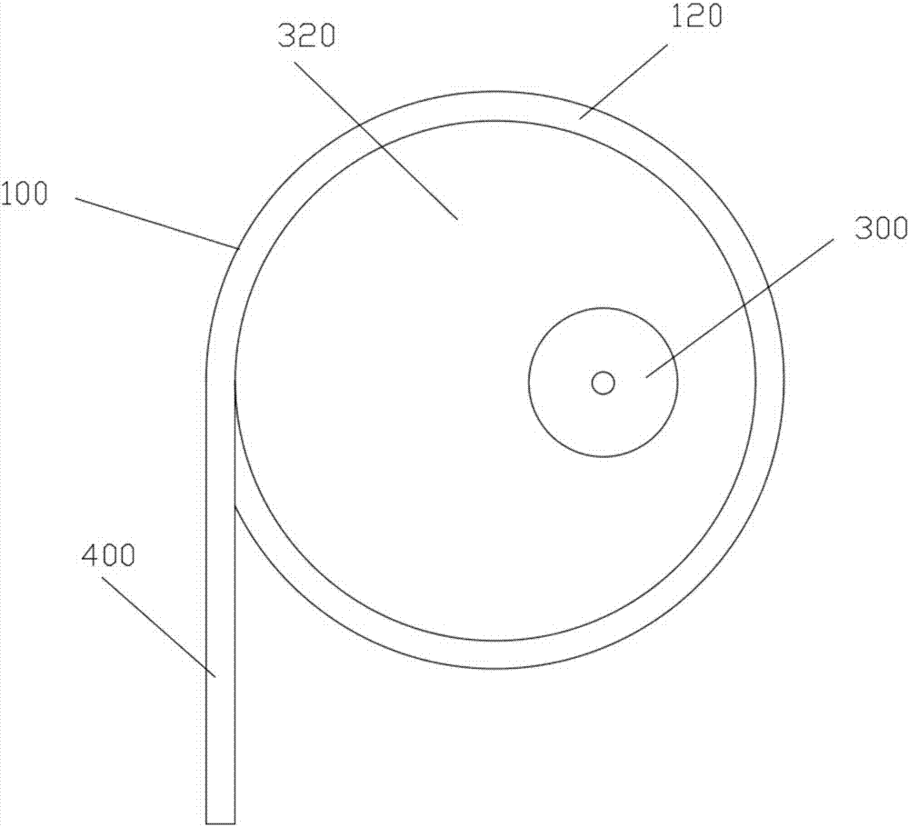
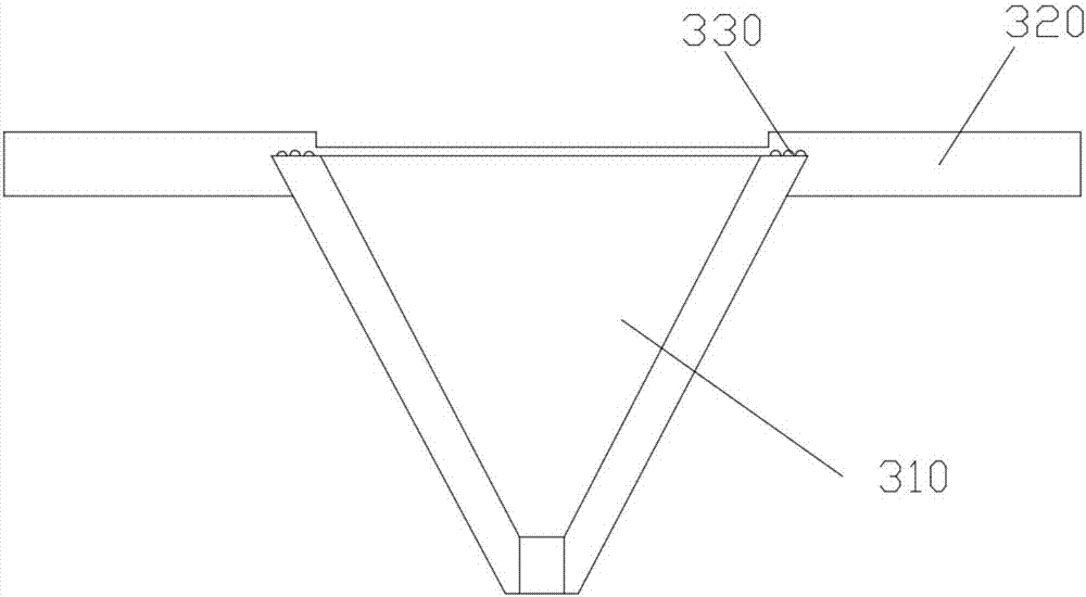
[0025] like figure 1 As shown, a feeding mechanism of a universal joint includes a barrel body 100, a rotating plate 110, a rotating assembly, a funnel assembly 300, and a feeding trough 400; the rotating plate 110 is located at the bottom of the barrel body 100, and the rotating plate 110 and the barrel body 100 rotating connection; the rotating assembly is located under the rotating plate 110, and the rotating assembly and the rotating plate 110 rotate synchronously; the funnel assembly 300 faces the barrel body 100, and the funnel assembly 300 is rotationally connected with the barrel body 100, and the inner wall of the barrel body 100 is provided with a transmission groove 120 , the initial position of the transfer trough 120 matches the position of the funnel 310 .

[0026] A bracket 320 is provided between the funnel assembly 300 and the barrel ...


PUM


Abstract

The invention discloses a feeding mechanism of universal joints. The feeding mechanism comprises a barrel body, a rotating plate, a rotating assembly, a funnel assembly and a feeding groove; the feeding groove is located at the top of the barrel body, and the top of the barrel body is provided with an opening connected with the feeding groove in a matched mode; the rotating plate is located at thebottom of the barrel body and is rotatably connected with the barrel body; the rotating assembly is located below the rotating plate, and the rotating assembly and the rotating plate rotate synchronously; and the funnel assembly faces the barrel body and is rotatably connected with the barrel body. Compared with the prior art, through rotating of the rotating plate, raw materials move towards theedge of the barrel body under action of centrifugal force, so that the raw materials simultaneously enter a conveying groove under action of the centrifugal force, automatic arranging and automatic feeding of the raw materials are achieved, meanwhile, the raw materials can only enter the barrel body only through the funnel assembly, so that the raw materials are only required to be poured throughthe funnel assembly and can be automatically sorted while passing the funnel assembly, therefore, the raw materials are not required to be sorted, and the workload of operators is reduced.

Description

technical field [0001] The invention belongs to the technical field of universal joint processing, and in particular relates to a universal joint feeding mechanism. Background technique [0002] At present, the common ways of torque transmission between spatially staggered shafts at home and abroad are mainly realized through universal joints. Universal joints mainly include single-section universal joints, double-section universal joints, and telescopic universal joints. Joints, spring loaded universal joints, fluid universal joints and ball universal joints. [0003] The universal joint is a machine that realizes variable-angle power transmission. It is used for changing the direction of the transmission axis. It is the "joint" part of the universal transmission of the automobile drive system. The combination of universal joint and transmission shaft is called universal joint transmission. On vehicles with front-engine rear-wheel drive, the universal joint transmission d...

Claims


Application Information

Patent Timeline
Patent Type & Authority Applications(China)
IPC IPC(8): B65G29/00B65G47/26
CPCB65G29/00B65G47/26
Inventor 黄春平
Owner PINGHU PINYAO MACHINERY AUTOMATION CO LTD
Why Eureka
Try Eureka