Radiation-resistant and bending-resistant reinforced optical cable

A radiation-resistant and reinforced technology, applied in the directions of light guides, optics, optical components, etc., can solve the problem that the optical cable is difficult to meet, and achieve the effect of light traction, excellent flame retardant performance, and high tensile strength

Pending Publication Date: 2018-05-01
JIANGSU ZHONGTIAN TECH CO LTD
View PDF5 Cites 3 Cited by
  • Summary
  • Abstract
  • Description
  • Claims
  • Application Information

AI Technical Summary

Problems solved by technology

Existing optical cables are difficult to meet the above requirements

Method used


Image

  • Radiation-resistant and bending-resistant reinforced optical cable
  • Radiation-resistant and bending-resistant reinforced optical cable
  • Radiation-resistant and bending-resistant reinforced optical cable

Examples


Embodiment 1

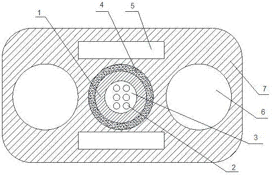
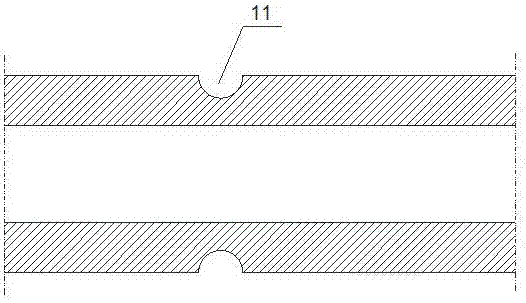
[0023] Such as figure 1 and figure 2 As shown, a radiation-resistant and lightning-proof reinforced optical cable includes a cable core, an armor layer and an outer sheath 7, and the cable core includes a loose tube 1, an even number of quartz optical fibers 2 coated with a radiation-resistant coating and fiber paste 3. The optical fiber 2 is set in the loose tube, and the fiber paste 3 is filled in the gap between the optical fiber and the loose tube. The loose tube is made of radiation-resistant and flame-retardant polytetrafluoroethylene. Due to the loose tube structure, the optical fiber is in a relaxed state in the loose tube, which can obtain effective and reasonable excess length and has good optical and mechanical properties. , At the same time, it can effectively shield the damage of radiation to the optical fiber and has the effect of flame retardancy. The outer wall of the loose tube 1 is provided with annular grooves 11 at equal intervals along the length direct...

Embodiment 2

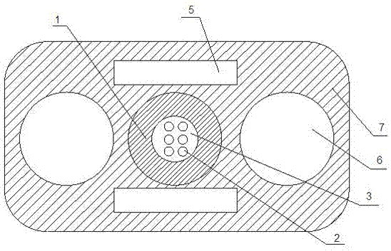
[0031] Such as figure 2 and image 3As shown, a radiation-resistant and lightning-proof reinforced optical cable includes a cable core, an armor layer and an outer sheath 7, and the cable core includes a loose tube 1, an even number of quartz optical fibers 2 coated with a radiation-resistant coating and fiber paste 3. The optical fiber 2 is set in the loose tube, and the fiber paste 3 is filled in the gap between the optical fiber and the loose tube. The loose tube is a PBT loose tube. Due to the loose tube structure, the optical fiber is in a relaxed state in the loose tube, and an effective and reasonable excess length can be obtained. It has good optical and mechanical properties. A non-metallic armor layer is set on the outside of the casing to further enhance the mechanical properties of the cable core, which has strong impact resistance against external forces and is not easily damaged. The outer wall of the loose tube 1 is provided with annular grooves 11 at equal i...


PUM


Abstract

The invention discloses a radiation-resistant and bending-resistant reinforced optical cable. The radiation-resistant and bending-resistant reinforced optical cable comprises a cable core, an armor layer and an outer sheath and is characterized in that the armor layer is arranged outside the cable core, the armor layer and the cable core are encapsulated in the outer sheath, the cable core comprises a loose sleeve, optical fibers and fiber paste, the optical fibers are arranged in the loose sleeve, the fiber paste is filled into the gap between the optical fibers and the loose sleeve, annulargrooves are arranged in the outer wall of the loose sleeve along the length direction in an equal-distance manner, the section of each groove is semicircular, the distance between every two adjacent grooves is 4mm, and the depth of each groove is half of the thickness of the loose sleeve. The radiation-resistant and bending-resistant reinforced optical cable has the advantages that the self-supporting cable is resistant to radiation and high temperature, flame-retardant, excellent in bending resistance, lightweight, capable of lowering transportation and laying costs and suitable for being laid in places such as nuclear power stations which have severe radiation and are high in optical cable bending performance requirements or places with high flame retardance and high temperature resistance requirements.

Description

technical field [0001] The invention relates to the technical field of communication optical cables, in particular to a radiation-resistant and bending-resistant reinforced optical cable. Background technique [0002] Optical cable erection lines often pass through areas with rodents and dense forests and birds. Usually, optical cables in such areas will be bitten by rats and pecked by birds for a period of time after laying, resulting in damage to the optical cable. At present, the following methods are mainly used for rodent-proof optical cables: 1) Chemical methods, usually by adding a certain proportion of anti-rat functional materials to the outer sheath material of the optical cable to achieve the anti-rat function, such as adding spicy However, the chemical method pollutes the environment and has a short timeliness. As time goes by, the mouse will gradually reduce the fear of the additive to the taste, and will also bite the optical cable to cause damage; 2) Physical ...

Claims


Application Information

Patent Timeline
Patent Type & Authority Applications(China)
IPC IPC(8): G02B6/44
CPCG02B6/443
Inventor 野绪波李新建缪小明沈冰冰钱慧慧朱嘉诚陈挺陈强
Owner JIANGSU ZHONGTIAN TECH CO LTD
Why Eureka
Try Eureka