Automatic hovering method of unmanned aerial vehicle (UAV)

A drone and hovering technology, applied in the direction of non-electric variable control, instrument, attitude control, etc., can solve the problems of high price, poor endurance of drones, complicated operation, etc., and achieve the effect of use

Pending Publication Date: 2018-05-01
GUANGZHOU WALKERA TECH CO LTD
View PDF7 Cites 4 Cited by
  • Summary
  • Abstract
  • Description
  • Claims
  • Application Information

AI Technical Summary

Problems solved by technology

[0007] Most of the drones currently on the market are hovering by GPS, ultrasonic detection, infrared detection, and optical flow positioning to achieve obstacle avoidance. For small drones, the more instruments they carry, the greater the en

Method used


Image

  • Automatic hovering method of unmanned aerial vehicle (UAV)
  • Automatic hovering method of unmanned aerial vehicle (UAV)
  • Automatic hovering method of unmanned aerial vehicle (UAV)

Examples


Embodiment 1

[0055] like figure 1 Shown, a kind of unmanned aerial vehicle automatic hovering method comprises unmanned aerial vehicle main body and optical flow positioning device, and described optical flow positioning device is arranged on unmanned aerial vehicle main body,

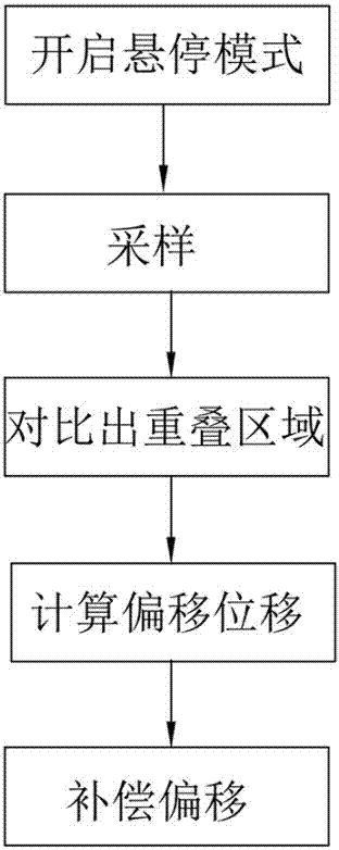
[0056] The automatic hovering method of the unmanned aerial vehicle may further comprise the steps:

[0057] S1: Turn on the hovering mode and record the initial hovering image;

[0058] S2: start sampling;

[0059] S3: Comparing the image sampled in the step S2 with the initial image to obtain the overlapping area of ​​the two;

[0060] S4: Calculate the displacement that needs to be offset according to the overlapping area in the step S3;

[0061] S5: According to the calculation result in the step S4, control the UAV to compensate the offset.

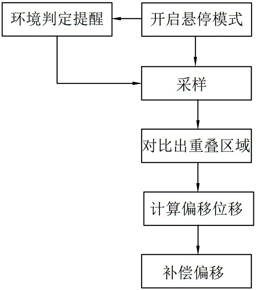
[0062] Further, such as figure 2 As shown, the automatic hovering method further includes a reminding step, and the reminding step includes reminding the user that ...

Embodiment 2

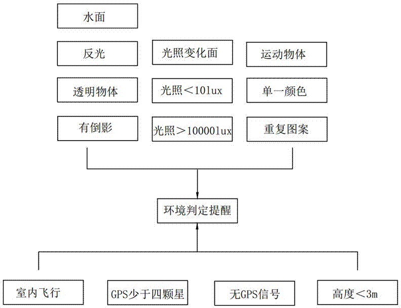
[0071] This embodiment is the specific implementation details of embodiment 1, such as Figure 6 As shown, when the drone needs to hover, the optical flow hovering system of the drone is turned on. On the one hand, the user can directly use the hovering according to his own judgment, or confirm whether to hover according to the internal judgment of the drone. . When the UAV reminder step is required, the optical flow camera judges the environment, when the ground is water, reflective, transparent, reflective, sharply changing, light10000lux, moving objects, In one or more cases of a single color or repeated patterns, the optical flow camera transmits signals to the main control board of the drone through the optical flow control board, and the main control board then transmits signals to the user end, generally the mobile end , to notify the user that the condition is not suitable for hovering, otherwise accidents may easily occur.

[0072] On the other hand, the optical flo...


PUM


Abstract

The invention relates to an automatic hovering method of a UAV. A UAV body and an optical flow positioning device arranged on the UAV are included. The automatic hovering method of the UAV comprises the following steps that S1) a hovering mode is started, and an initial hovering image is recorded; S2) sampling is started; S3) an image sampled in the step 2) is compared with the initial image to obtain an overlapped area therebetween; S4) according the overlapped area in the step S3), displacement which needs offset is calculated; and S5) according to a calculation result in the step S4), the UAV is controlled to compensate the offset. The method is simple in steps, time from start to realization of hovering is very short, optical flow positioning hovering instead of an optical flow positioner is used, the total cost of the UAV is reduced, the AUV is lighter and saves more energy, and accurate positioning can be realized. The whole calculation process is convenient and rapid, and the UAV can be corrected rapidly in the hovering process and returns to the original position.

Description

technical field [0001] The invention belongs to the technical field of unmanned aerial vehicles, and in particular relates to an automatic hovering method of an unmanned aerial vehicle. Background technique [0002] Thanks to the advancement of sensors, actuators, processors and other technologies and the reduction of related costs, combined with the advantages of this part, it is possible to build semi-automatic and fully automatic multi-rotor aircraft. The research on UAV control technology is one of the hotspots of domestic and foreign UAV R&D companies, universities, and research institutions, such as pocket UAVs, autonomous avoidance and dancing UAVs, etc., which make UAVs miniaturized , intelligence, and automatic control precision have reached a very high level, and the existing drones are also widely used in military, civilian and other fields, such as self-portrait and synchronous sending to Moments, aerial photography, high-level equipment in factories Operational...

Claims


Application Information

Patent Timeline
IPC IPC(8): G05D1/10G05D1/08
CPCG05D1/0858G05D1/102
Inventor 罗之洪李奔夏烨罗强
Owner GUANGZHOU WALKERA TECH CO LTD
Why Eureka
Try Eureka