A Height Platform Adjustment Device Applied to Assembly of Fuel Main Pipe and Its Application Method
What is Al technical title?
Al technical title is built by PatSnap Al team. It summarizes the technical point description of the patent document.
A fuel manifold and adjusting device technology, applied in the field of aviation parts assembly, can solve the problems of hidden dangers in the assembly of the main combustion chamber fuel pipeline, high risk factor of the main combustion chamber casing, low work efficiency, etc., so as to improve the assembly quality, The effect of reducing the difficulty of operation and improving work efficiency
Active Publication Date: 2019-04-23
SHENYANG LIMING AERO-ENGINE GROUP CORPORATION
View PDF7 Cites 0 Cited by
Summary
Abstract
Description
Claims
Application Information
AI Technical Summary
This helps you quickly interpret patents by identifying the three key elements:
Problems solved by technology
Method used
Benefits of technology
Problems solved by technology
[0002] During the assembly process of the fuel pipeline of the main combustion chamber, due to the complicated external pipelines and strict requirements on the height of the casing of the main combustion chamber, the traditional assembly usually adopts hoisting of the casing of the main combustion chamber, and the lug of the fuel main pipe is installed on the main combustion chamber. In the ear seat of the combustion chamber casing, align and connect the multiple fuel injection pipes on the fuel manifold with the nozzles of the main combustion chamber casing. Continuously adjust the installation position, and lock it after adjusting to the required position. During the adjustment process, the main combustion chamber casing is hoisted, with large disturbance, difficult operation and low work efficiency, and hoisting the main combustion chamber casing The risk factor is high, which makes the main combustion chamber fuel pipeline assembly a safety hazard
Method used
Image
Click on the blue label to locate the original text in one second.
Reading with bidirectional positioning of images and text.
Examples
Embodiment Construction
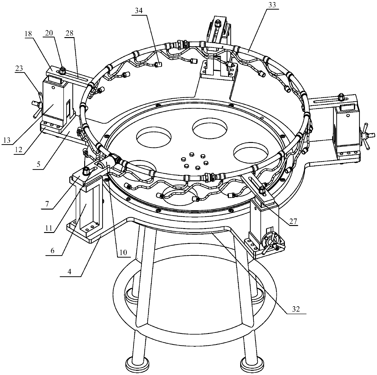
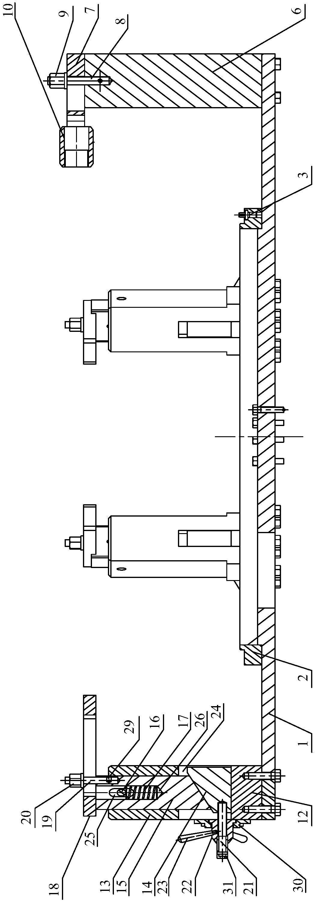
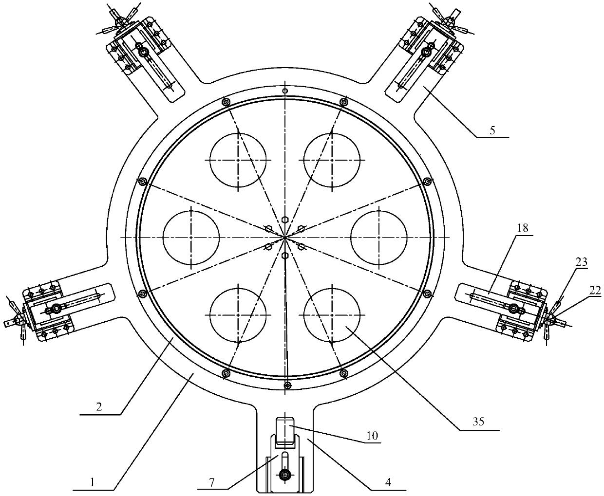
[0025] In order to solve the problems existing in the assembly process of the existing main combustion chamber fuel pipeline, such as Figure 1 to Figure 4 As shown, the present invention provides a height platform adjustment device applied to the assembly of the fuel main pipe. The height platform adjustment device applied to the assembly of the fuel main pipe includes a circular base 1, a positioning ring 2, a positioning pin 3, an angular positioning device and height adjustment device;
[0026] The positioning ring 2 is installed on the circular base 1, and the positioning ring 2 is equipped with a plurality of positioning pins 3 in the circumferential direction. The positioning pins 3 are used for positioning the main combustion chamber casing. The circular base 1 is provided with a first protruding End 4 and a plurality of second protruding ends 5, the first protruding end 4 and the second protruding end 5 are evenly arranged along the circumference of the circular base ...
PUM
Abstract
The invention provides a height platform adjusting device applied to the assembly of a fuel oil main pipe and a using method of the height platform adjusting device, and belongs to the technical fieldof assembly of aviation parts. The height platform adjusting device applied to the fuel oil main pipe assembly comprises a round base, a positioning ring, positioning pins, an angular positioning device and a height adjusting device, wherein the positioning ring is arranged on the round base, and a plurality of positioning pins are arranged on the positioning ring in the circumferential direction. The round base is provided with a first extending end and a plurality of second extending ends, the angular positioning device is arranged on the first extending end, and each second extending end is provided with a height adjusting device. Each angular positioning device comprises a positioning support, an angle plate, a first threaded rod, a first nut and a threaded sleeve. Each height adjusting device comprises a base plate, a guide seat, a wedge block, a sliding column, a dowel, a spring, a support plate, a second threaded rod, a second nut, a third threaded rod, a third nut and a handle. According to the device, the assembly of the fuel oil main pipe can be realized, the operation difficulty is lowered, a main combustion chamber is not required to be hoisted, and the safety is guaranteed.
Description
technical field [0001] The invention relates to the technical field of assembly of aviation parts, in particular to a height platform adjustment device and a use method applied to the assembly of a fuel main pipe. Background technique [0002] During the assembly process of the fuel pipeline of the main combustion chamber, due to the complicated external pipelines and strict requirements on the height of the casing of the main combustion chamber, the traditional assembly usually adopts hoisting of the casing of the main combustion chamber, and the lug of the fuel main pipe is installed on the main combustion chamber. In the ear seat of the combustion chamber casing, align and connect the multiple fuel injection pipes on the fuel manifold with the nozzles of the main combustion chamber casing. Continuously adjust the installation position, and lock it after adjusting to the required position. During the adjustment process, the main combustion chamber casing is hoisted, with l...
Claims
Application Information
Patent Timeline
Application Date:The date an application was filed.
Publication Date:The date a patent or application was officially published.
First Publication Date:The earliest publication date of a patent with the same application number.
Issue Date:Publication date of the patent grant document.
PCT Entry Date:The Entry date of PCT National Phase.
Estimated Expiry Date:The statutory expiry date of a patent right according to the Patent Law, and it is the longest term of protection that the patent right can achieve without the termination of the patent right due to other reasons(Term extension factor has been taken into account ).
Invalid Date:Actual expiry date is based on effective date or publication date of legal transaction data of invalid patent.
Patent Type & Authority Patents(China)
IPC IPC(8): B23P19/00B25H1/02B25H1/14
CPCB23P19/00B23P2700/01B25H1/02B25H1/14
Inventor 彭会文张娟阚敏李培阳彭晟尧
Owner SHENYANG LIMING AERO-ENGINE GROUP CORPORATION