
Grinding working table for casting molds

A technology for casting molds and worktables, which is used in manufacturing tools, grinding workpiece supports, grinders, etc., and can solve the problems of grinding workers such as soreness of lumbar muscles, inability to stand upright, and heavy mold weight.

Inactive Publication Date: 2018-05-04
DONGGUAN LIANZHOU INTPROP OPERATION MANAGEMENT CO LTD
View PDF6 Cites 3 Cited by
  • Summary
  • Abstract
  • Description
  • Claims
  • Application Information

AI Technical Summary

Problems solved by technology

Due to the influence of mold structure, style, model and other factors, the mold fixed on the grinding table sometimes requires the grinder to bend over to work, which will easily cause lumbar muscle pain or even inability to stand upright for a long time, and the mold itself is heavy. , when changing the grinding position, the operator needs to move continuously, which is time-consuming and laborious. It takes up to 7 to 8 hours to polish a pair of molds under the existing technology

Method used


Image

  • Grinding working table for casting molds
  • Grinding working table for casting molds
  • Grinding working table for casting molds

Examples


Embodiment Construction

[0021] The specific implementation manners of the present invention will be further described in detail below in conjunction with the accompanying drawings and embodiments. The following examples are used to illustrate the present invention, but are not intended to limit the scope of the present invention.

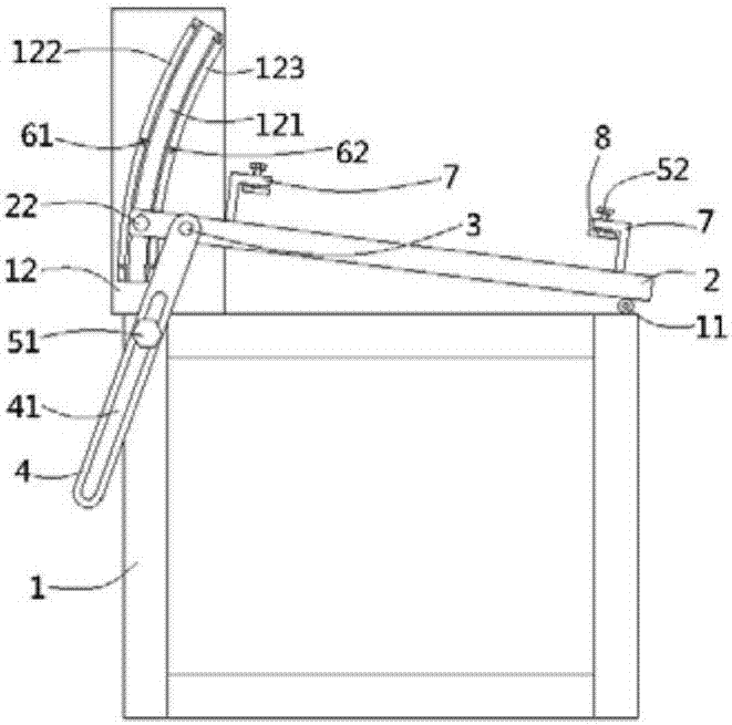
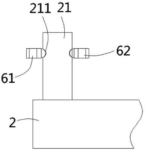
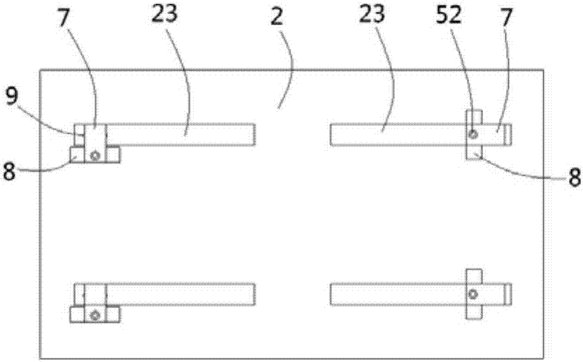
[0022] see figure 1 , figure 2 , a grinding workbench for casting moulds, according to the present invention, includes a bracket 1, the front side of the upper end of the bracket 1 is hinged to one end of the grinding platform 2 through a hinge 11, and the other end of the grinding platform 2 is on the left side The wall is plugged and fixed with a pillar 3, the pillar 3 is hinged with a positioning rod 4, and a guide groove 41 is formed on the positioning rod 4, and the guide groove 41 is in the shape of a strip along the longitudinal direction of the positioning rod 4, guiding The groove 41 runs through the left and right side walls of the positioning rod 4, the first...


PUM


Abstract

The invention discloses a grinding working table for casting molds. The grinding working table comprises a bracket; the front side of the upper end of the bracket is hinged to one end of the grindingtable through a hinge, the right side wall of the other end of the grinding table is fixedly connected with a limiting column in an inserted mode, a support plate is formed on the bracket, and an arc-shaped limiting groove is formed on the side wall of the support plate; the limiting column is connected with the limiting groove in an inserted mode, a pair of limiting holes is formed in the limiting column, an upper installation groove and a lower installation groove are formed on the side wall of the support plate of the upper and lower sides of the limiting groove, and the upper installationgroove and the lower installation groove are connected with upper ball plungers and lower ball plungers in a threaded mode; and moving grooves are formed in the upper and lower sides of the upper endsurface of the grinding table, L-shaped clamping plates are connected with the interiors of the moving grooves in an inserted mode, second bolts are connected to the upper ends of the clamping platesin a threaded mode, pressing plates are fixedly connected to the lower ends of the second bolts, multiple pairs of shrinkage pools are formed on the opposite inner walls of the moving grooves, and thelower ends of the clamping plates are connected to a pair of positioning ball plungers in a threaded mode. The height of the grinding table can be adjusted, the grinding time is saved, and the grinding working table is suitable for grinding molds with different types.

Description

Technical field: [0001] The invention relates to the technical field of moulds, in particular to a grinding workbench for casting moulds. Background technique: [0002] After the casting mold is produced, the surface is prone to roughness, strain, corrosion, pitting and other adverse conditions, requiring workers to polish and repair the mold. Due to the influence of mold structure, style, model and other factors, the mold fixed on the grinding table sometimes requires the grinder to bend over to work, which will easily cause lumbar muscle pain or even inability to stand upright for a long time, and the mold itself is heavy. , When changing the grinding position, the operator needs to move constantly, which is time-consuming and laborious. It takes up to 7 to 8 hours to polish a pair of molds in the prior art. [0003] In view of the above-mentioned defects, the designer actively researches and innovates in order to create a new type of structure for the grinding workbench ...

Claims


Application Information

Patent Timeline
Patent Type & Authority Applications(China)
IPC IPC(8): B24B41/06B24B41/00B24B19/20B24B41/02
CPCB24B41/06B24B19/20B24B41/00B24B41/02
Inventor 杨勇
Owner DONGGUAN LIANZHOU INTPROP OPERATION MANAGEMENT CO LTD
Learn More