Production process of organic gel surface layer concrete porous water permeable bricks

A technology of concrete and organic glue, which is applied in the direction of manufacturing tools, ceramic molding machines, cement mixing devices, etc., can solve the problems of infiltration into the ground, poor water permeability of permeable bricks, etc., to achieve enhanced service life, good water seepage performance, and improved water seepage performance Effect

Active Publication Date: 2018-05-04
QUANGONG MACHINERY
View PDF5 Cites 0 Cited by
  • Summary
  • Abstract
  • Description
  • Claims
  • Application Information

AI Technical Summary

Problems solved by technology

In this way, when it rains, the rainwater will seep into the ground from the gaps between the bricks; the existing permeable bricks are generally made of materials such as cement, gravel and cement, and then, during the compounding process, due to the uneven mixing of the raw materials, Poor water permeability of permeable bricks

Method used


Image

  • Production process of organic gel surface layer concrete porous water permeable bricks
  • Production process of organic gel surface layer concrete porous water permeable bricks
  • Production process of organic gel surface layer concrete porous water permeable bricks

Examples


Embodiment 1

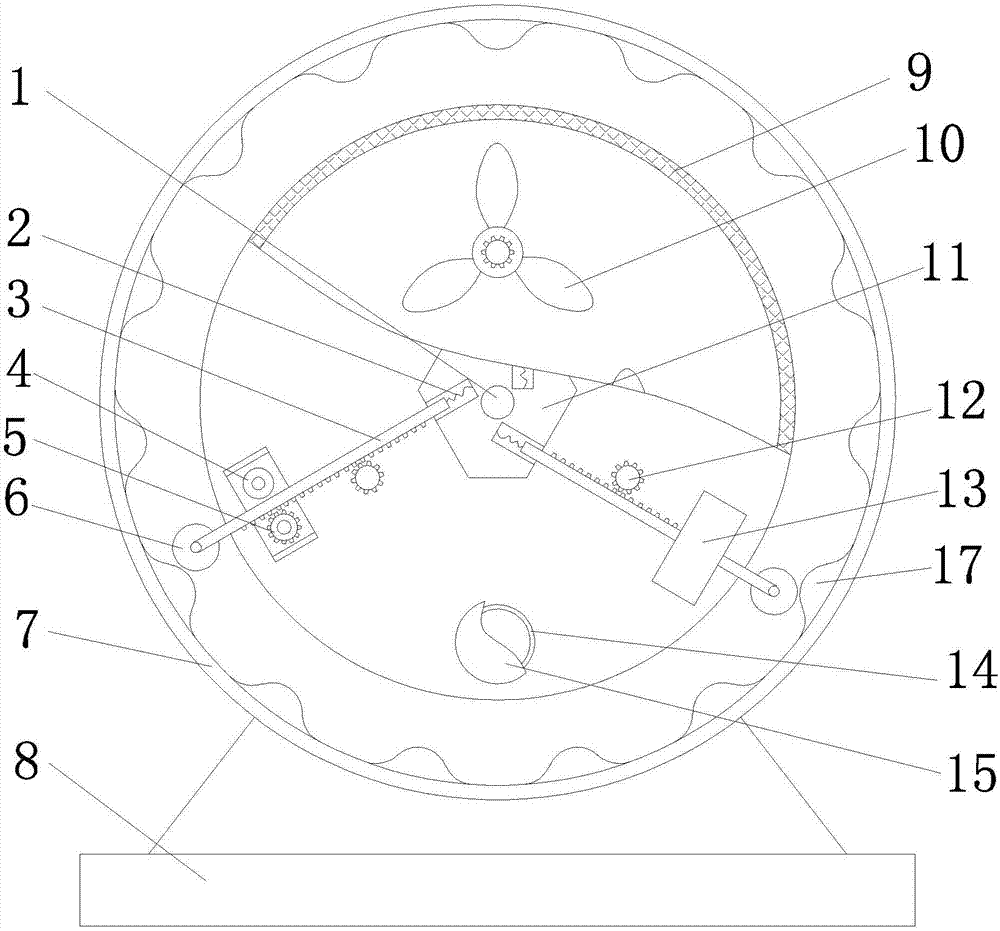
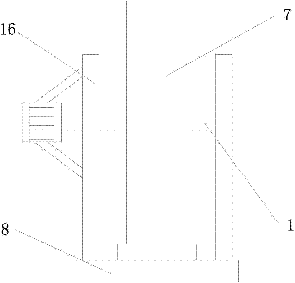
[0023] refer to Figure 1-2 , a concrete mixing device for the surface layer of organic gelling material, comprising a base 8, the top of the base 8 is respectively fixedly connected with a circular frame 7 and two supports 16, and the circular frame 7 is located between the two supports 16, and the circular The inner circle of the frame 7 is provided with a circular mixing bucket 9, and the center of the circular mixing bucket 9 is fixedly inserted with a first rotating shaft 1, and one end of the first rotating shaft 1 is rotationally connected with the side wall of one of the brackets 16, and the first rotating shaft The other end of 1 runs through another bracket 16 and is connected with the output end of the motor, and the side wall of the motor is connected with the bracket 16 through a support rod, and the inner wall of the circular mixing bucket 9 is rotatably connected with an eccentrically arranged second rotating shaft, the second rotating shaft A stirring paddle 10...

Embodiment 2

[0031] refer to Figure 1-2 , a concrete mixing device for the surface layer of organic gelling material, comprising a base 8, the top of the base 8 is respectively fixedly connected with a circular frame 7 and two supports 16, and the circular frame 7 is located between the two supports 16, and the circular The inner circle of the frame 7 is provided with a circular mixing bucket 9, and the center of the circular mixing bucket 9 is fixedly inserted with a first rotating shaft 1, and one end of the first rotating shaft 1 is rotationally connected with the side wall of one of the brackets 16, and the first rotating shaft The other end of 1 runs through another bracket 16 and is connected with the output end of the motor, and the side wall of the motor is connected with the bracket 16 through a support rod, and the inner wall of the circular mixing bucket 9 is rotatably connected with an eccentrically arranged second rotating shaft, the second rotating shaft A stirring paddle 10...


PUM


Abstract

The invention discloses an organic gel surface layer concrete stirring device. The organic gel surface layer concrete stirring device comprises a base. The top of the base is fixedly connected with acircular frame and two supports. The circular frame is located between the two supports. A circular stirring barrel is arranged on an inner ring of the circular frame. A first rotary shaft is fixedlyinserted in the center of the circular stirring barrel. One end of the first rotary shaft is rotatably connected with the sidewall of one support. The organic gel surface layer concrete stirring device is simple in structure. A surface layer is formed in the manner that red sand and yellow sand are bonded through asphalt and synthetic resin and other organic gel, and the service life of the surface layer can be prolonged. Moreover, the red sand and the yellow sand are mixed, the color is bright and catchy, and the aesthetic property is improved. A bottom layer is prepared from 42.5# ordinary Portland cement and gravels and has high strength and porosity. The water permeability performance can be improved. Organic gel surface layer concrete porous water permeable bricks prepared through thedevice are solid, durable, attractive and good in water permeability performance through combination of the surface layer and the bottom layer.

Description

technical field [0001] The invention relates to the technical field of building materials, in particular to a production process of an organic gelling material surface layer concrete pore permeable brick. Background technique [0002] Permeable bricks originated in the Netherlands. During the process of building a city from the sea, the Dutch found that the ground after the seawater was drained would cause continuous land subsidence due to long-term lack of contact with water. Once the dykes on the coastline are washed away, the seawater will quickly rush to cities much lower than sea level and submerge the entire coastal city. In order to prevent the ground from sinking, the Dutch made a small pavement brick with a length of 200 mm, a width of 100 mm, and a height of 50 or 60 mm, which was laid on the street surface, and a gap of 2 mm was reserved between the bricks. In this way, when it rains, the rainwater will seep into the ground from the gaps between the bricks; the e...

Claims


Application Information

Patent Timeline
Patent Type & Authority Applications(China)
IPC IPC(8): B28B3/00B28B11/24B28B15/00B28B17/00B28C5/08
CPCB28B3/00B28B11/245B28B15/00B28B17/00B28C5/08
Inventor 傅鑫源傅炳煌
Owner QUANGONG MACHINERY
Why Eureka
Try Eureka