A screw-driven flap gate

A flap gate and screw drive technology, applied in the field of flap gates, can solve problems such as difficulty in accurately controlling the opening, slow hydraulic oil return speed, affecting flood safety, etc., achieve precise water level and flow control, and fast opening and closing speed. , the effect of improving safety

Active Publication Date: 2019-11-05
陈文重
View PDF2 Cites 0 Cited by
  • Summary
  • Abstract
  • Description
  • Claims
  • Application Information

AI Technical Summary

Problems solved by technology

However, the failure of the hydraulic cylinder of any one of the units will cause the entire hydraulic lifting dam or hydraulic flap dam to fail to achieve the function of retaining water
[0005] 2. The hoist is essentially a hydraulic cylinder. The hydraulic cylinder is prone to leakage. The leakage will cause the door body to be unable to maintain a fixed position for a long time, and the leaked hydraulic oil will also pollute the water body.
[0006] 3. Unable to lock at any position
The hydraulic lifting dam or the hydraulic flap dam can only be locked at one position when it is fully closed, so that the hydraulic cylinder can be unloaded. The dam can only rely on the hydraulic pressure in the hydraulic cylinder to support the door body, and because the aforementioned hydraulic cylinder is easy to leak, without locking, the hydraulic cylinder is difficult to keep the door body in a fixed position for a long time, resulting in hydraulic lift dam Or the hydraulic flap dam cannot be partially opened for a long time, or the opening of the door body unit is inconsistent and uneven due to the different leakage of each hydraulic cylinder, which is not conducive to controlling the discharge flow and also affects the appearance
[0007] 4. It is difficult to precisely control the opening and adjust the flow
However, the hydraulic cylinders of hydraulic lifting dams or hydraulic flap dams are installed underwater, and the reliability of the opening gauge working underwater is low. Therefore, it is impossible to precisely adjust the water level and flow by controlling the opening angle of the door body
[0008] 5. Long opening time
When the pressure difference between the front and back of the door body is small, the water pressure is not large or the diameter of the hydraulic pipeline is small, the return speed of the hydraulic oil is very slow, causing the door body to open for a long time, which affects the safety of flood discharge in case of sudden flood

Method used


Image

  • A screw-driven flap gate
  • A screw-driven flap gate
  • A screw-driven flap gate

Examples


Embodiment Construction

[0036] In the following, the present invention will be further elaborated in combination with specific implementation and with reference to the accompanying drawings.

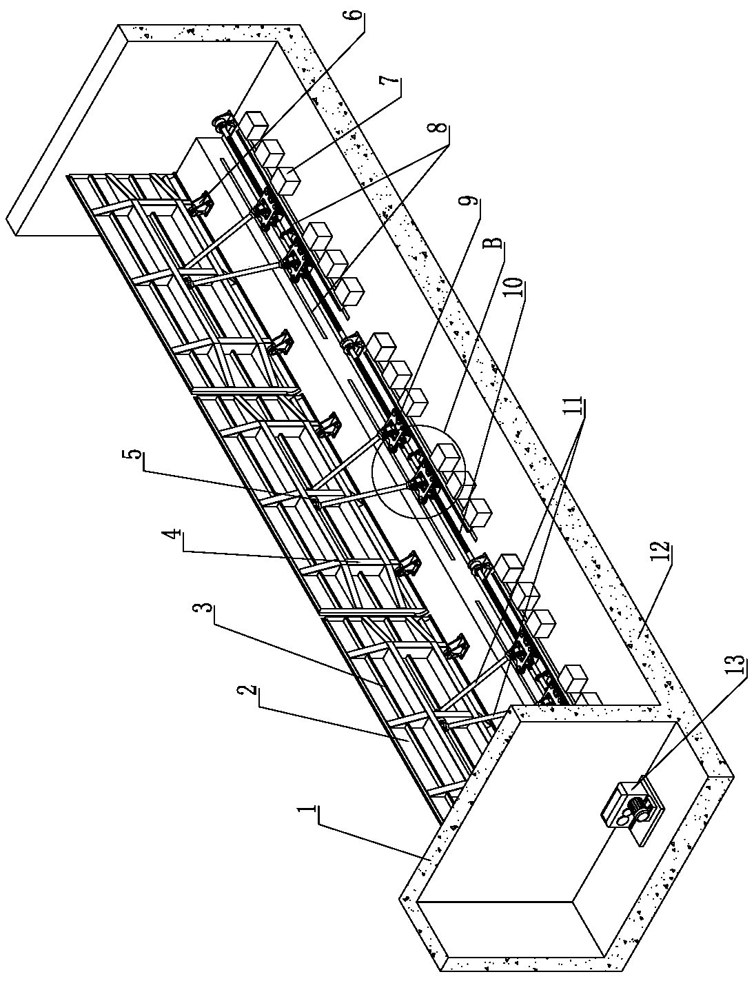
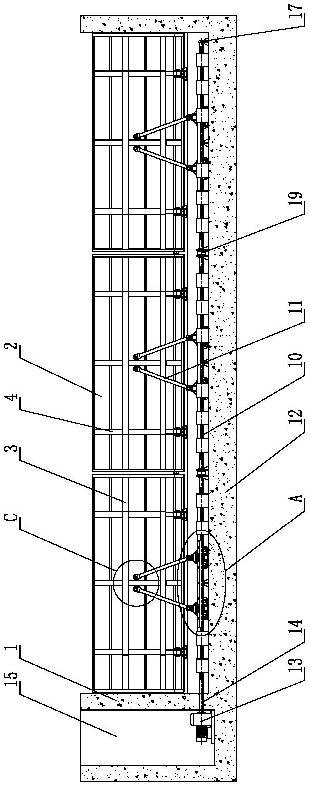
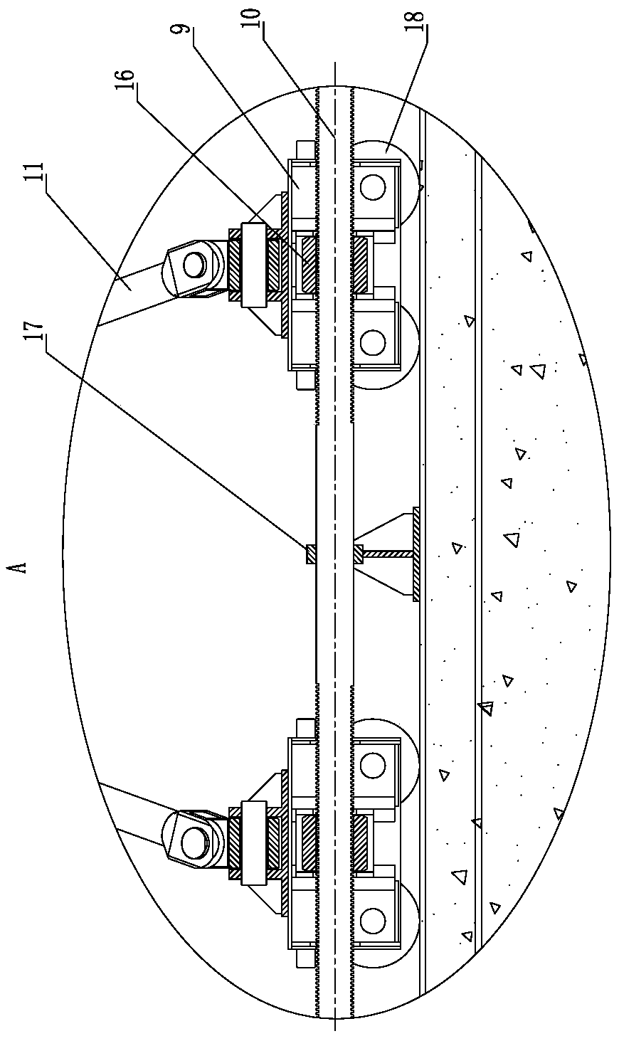
[0037] as attached Figure 1-9 As shown, the structure of a spiral-driven flap gate of the present invention mainly includes gate walls 1 arranged on both sides of the river channel, a bottom plate 12 arranged at the bottom of the river channel, and a gate body 2 arranged between the gate wall 1 and the bottom plate 12, The bottom plate 12 is provided with several hinge seats 6 at intervals, and the bottom of the door body 2 is hinged on the hinge seats 6, so that the door body 2 can rotate around the hinge seats 6 as a whole. The bottom of the body 2 can be hinged with the hinge seat 6 one by one with pin shafts; for the convenience of manufacture and installation, the door body 2 is composed of several unit door leaves, as shown in the figure, the door body 2 is composed of three unit door leaves, and the uni...


PUM


Abstract

The invention discloses a screw-driven flap gate applied to the field of water conservancy facilities. The bottom of a door body of the screw-driven flap gate is hinged to hinge seats. The back side of the door body is provided with one or more support rod pairs. The upper ends of two support rods in each support rod pair are hinged to the door body, and the lower ends of the two support rods in each support rod pair are hinged to a trolley. Each trolley is provided with a nut. A base plate is provided with tracks in the width direction of a river way. The trolleys are movably mounted in the tracks. The river way is internally provided with a threaded rod. The threaded rod is provided with rightwards-screwing threaded sections and leftwards-screwing threaded sections. The nuts on all the trolleys are connected with the rightwards-screwing threaded sections and leftwards-screwing threaded sections in an engaged manner correspondingly. The shaft end of the threaded rod is connected witha rotation driving mechanism. According to the screw-driven flap gate, the threaded rod is driven by the rotation driving mechanism to rotate; the included angle of every two support rods is driven tochange through the corresponding nut; and the door body is pushed to rotate to be erected to stop water or lie down to drain the water. The screw-driven flap gate is high in reliability and can be locked at any open degree; the opening and closing speed is high; and no leakage or pollution is caused. The screw-driven flap gate can replace an existing gate and is applied to the fields such as river way flood prevention and irrigation.

Description

technical field [0001] The invention relates to a hydraulic engineering facility, in particular to a flap gate. Background technique [0002] In the prior art, the flap gates used for retaining and storing water in many water conservancy projects are usually operated by hydraulic cylinders, including hydraulic lifting gates, hydraulic flap gates, etc. Among them, there is a bottom horizontal axis flap gate whose structure mainly includes The sluice walls set on both sides of the river, between the sluice walls, there are door leaves used to block the river water, the bottom of the door leaves is connected to the bottom shaft, and the two ends of the bottom shaft pass through the sluice wall and extend into the hoist chamber, the shaft of the bottom shaft The end of the hoist is connected with one end of the crank arm. There is a hoist in the hoist room. The piston rod extension end of the hoist is connected with the other end of the crank arm. There are several hinge seats a...

Claims


Application Information

Patent Timeline
Patent Type & Authority Patents(China)
IPC IPC(8): E02B7/44E02B13/02
CPCE02B7/44E02B13/02
Inventor 陈文重
Owner 陈文重
Why Eureka
Try Eureka