Double-T-type four-level inverter unit, application circuits containing double-T-type four-level inverter unit and modulation methods of circuits

A technology of inverter unit and inverter circuit, which is applied to electrical components, conversion devices for converting AC power input to DC power output, and output power, etc. And other issues

Active Publication Date: 2018-05-04
CHONGQING UNIV
View PDF7 Cites 4 Cited by
  • Summary
  • Abstract
  • Description
  • Claims
  • Application Information

AI Technical Summary

Problems solved by technology

The topology of the diode-clamped multilevel inverter circuit has disadvantages such as difficulty in equalizing the voltage of each capacitor on the DC bus side and uneven voltage pressure.
The flying capacitor voltage

Method used


Image

  • Double-T-type four-level inverter unit, application circuits containing double-T-type four-level inverter unit and modulation methods of circuits
  • Double-T-type four-level inverter unit, application circuits containing double-T-type four-level inverter unit and modulation methods of circuits
  • Double-T-type four-level inverter unit, application circuits containing double-T-type four-level inverter unit and modulation methods of circuits

Examples


Embodiment 1

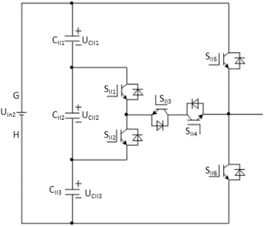
[0168] A double-T-type four-level inverter unit is mainly divided into two types: a common-emitter double-T-type four-level inverter unit and a common-collector double-T-type four-level inverter unit.

[0169] Further, the common-emitter double-T four-level inverter unit requires five independent driving power sources. The common-collector double T-type four-level inverter unit requires four independent driving power sources.

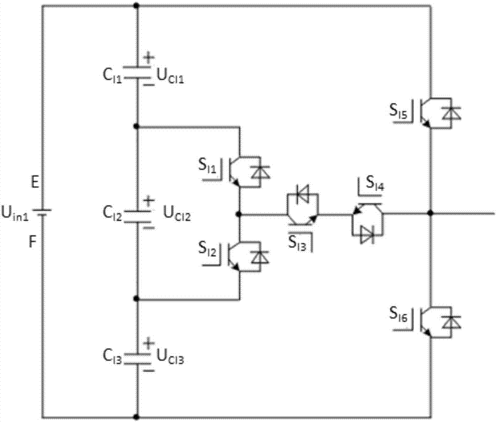
[0170] The circuit structure of the common-emitter double T-type four-level inverter unit is as follows:

[0171] Power U in1 The end where the positive pole is located is marked as terminal E, and the end where the negative pole is located is marked as terminal F.

[0172] The E terminal is sequentially connected in series with a capacitor C I1 , capacitance C I2 and capacitance C I3 Then connect the F terminals in series.

[0173] The E terminal series capacitor C I1 After connecting the switch tube S I1 collector. The switching tube S I1 Th...

Embodiment 2

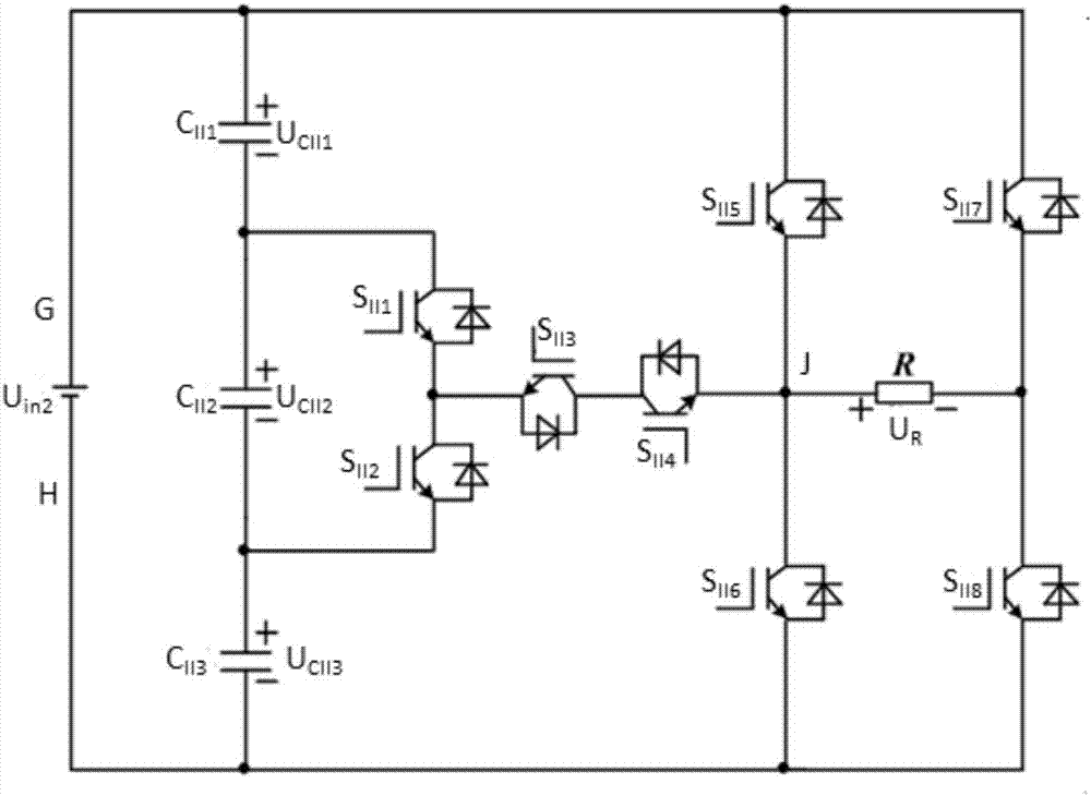
[0200] A single-phase four-level inverter circuit composed of the double-T-type four-level inverter unit, mainly comprising a common-collector double-T-type four-level inverter unit, a switch tube S II7 , switch tube S II8 and resistor R.

[0201] The structure of the single-phase four-level inverter circuit is mainly as follows:

[0202] The switching tube S of the common-collector double T-type four-level inverter unit II5 The collector is connected in series with the switching tube S II7 collector.

[0203] The switching tube S II7 The base is floating. The switching tube S II7 The emitter of the series switch S II8 collector. The switching tube S II7 The collector of the common collector is connected in series with the capacitor C of the common-collector double T-type four-level inverter unit II1 . The switching tube S II7 The collector is connected in series with the G terminal of the common-collector double T-type four-level inverter unit.

[0204] The switc...

Embodiment 3

[0208] A three-phase dual-T-type four-level inverter circuit composed of the double-T-type four-level inverter unit, the circuit structure is mainly as follows:

[0209] Power U in3 The end where the positive pole is located is marked as the K end, and the end where the negative pole is located is marked as the L end.

[0210] The K terminal is sequentially connected in series with a capacitor C III1 , capacitance C III2 and capacitance C III3 Then connect the L terminals in series.

[0211] The K terminal series capacitor C III1 After connecting the switch tube S a3 collector. The switching tube S a3 The base is floating. The switching tube S a3 The emitter of the series switch S a4 collector. The switching tube S a3 The emitter of the series switch S a2 the emitter.

[0212] The switching tube S a4 The base is floating. The switching tube S a4 The emitter series capacitor C III3 .

[0213] The switching tube S a2 The base is floating. The switching tube ...


PUM


Abstract

The invention discloses a double-T-type four-level inverter unit, application circuits containing the double-T-type four-level inverter unit and modulation methods of the circuits. The double-T-type four-level inverter unit mainly comprises a common-emitter double-T-type four-level inverter unit and a common-collector double-T-type four-level inverter unit; a single-phase four-level inverter circuit and a three-phase double-T-type four-level inverter circuit mainly comprise the common-collector double-T-type four-level inverter unit. The modulation methods mainly comprises two modulation methods of the single-phase four-level inverter circuit and one modulation method of the three-phase double-T-type four-level inverter circuit. Increase of output voltage level of the double-T-type four-level inverter unit and the application circuit topology thereof is favorable for reduction of the harmonic distortion of output voltage.

Description

technical field [0001] The invention relates to the technical field of inverter circuits for grid-connected power generation, in particular to a double T-type four-level inverter unit and its application circuit and modulation method. Background technique [0002] In recent years, there are mainly three relatively mature topological structures of multilevel inverter circuits: diode clamp type, cascade type and flying capacitor type. The topology of the diode-clamped multilevel inverter circuit has disadvantages such as difficulty in equalizing the voltage of each capacitor on the DC bus side and uneven voltage pressure. The cascaded multi-level inverter circuit topology requires multiple independent DC power supplies without sharing ground when active power needs to be provided. The flying capacitor voltage of the flying capacitor type inverter circuit is automatically balanced, and human intervention and adjustment cannot be performed, which will cause a certain voltage de...

Claims


Application Information

Patent Timeline
IPC IPC(8): H02M7/483H02M1/14
CPCH02M1/14H02M7/483
Inventor 陈剑飞李剑
Owner CHONGQING UNIV
Why Eureka
Try Eureka