High-precision stick-slip piezoelectric rotating table and driving method thereof

A high-precision, rotary table technology, used in piezoelectric/electrostrictive or magnetostrictive motors, generators/motors, electrical components, etc. question

Active Publication Date: 2018-05-04
CHANGCHUN UNIV OF TECH
View PDF13 Cites 8 Cited by
  • Summary
  • Abstract
  • Description
  • Claims
  • Application Information

AI Technical Summary

Problems solved by technology

[0004] In order to solve the technical problems of the existing stick-slip piezoelectric rotary platform, such as small output thrust, low positioning accuracy, slo

Method used


Image

  • High-precision stick-slip piezoelectric rotating table and driving method thereof
  • High-precision stick-slip piezoelectric rotating table and driving method thereof
  • High-precision stick-slip piezoelectric rotating table and driving method thereof

Examples


specific Embodiment approach 1

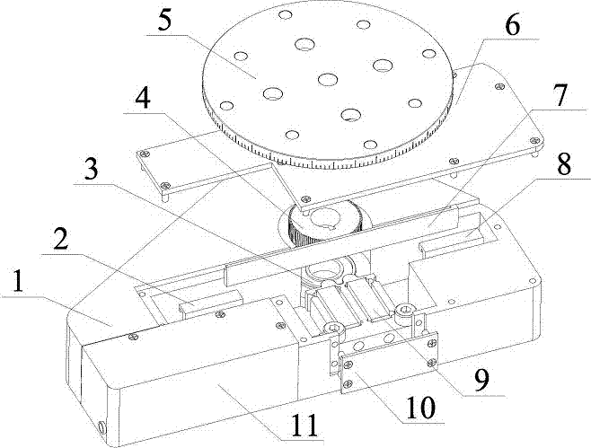
[0056] Specific implementation mode one: combine Figure 1~Figure 14 This embodiment is described. This embodiment provides a specific implementation of a high-precision piezoelectric stick-slip rotary table that realizes double-stacked double-drive foot stator assemblies. The specific implementation of the high-precision piezoelectric stick-slip rotary table with double-stacked double-drive foot stator assembly is described as follows:

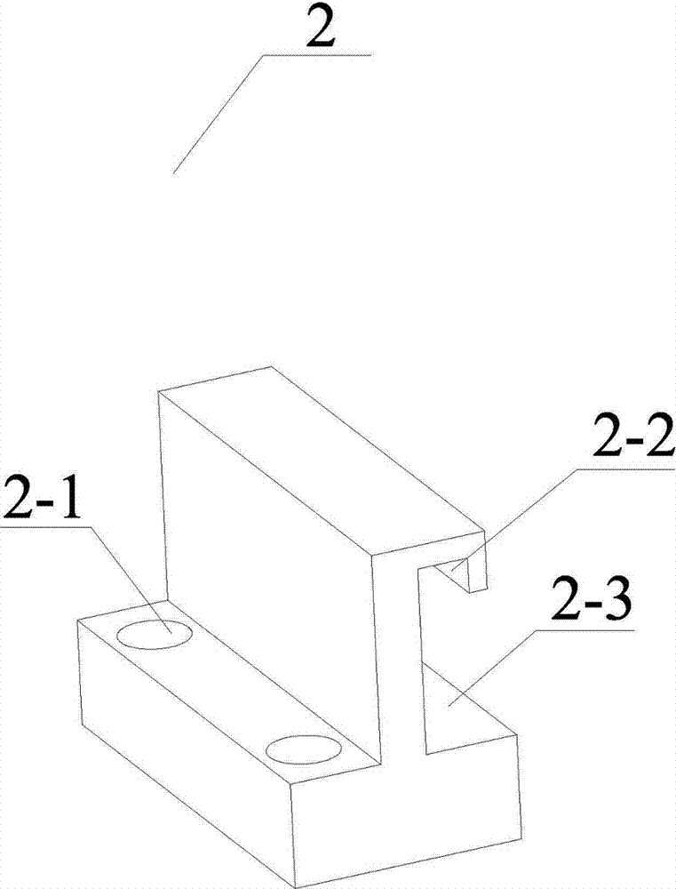
[0057] The high-precision piezoelectric stick-slip rotary table of the dual-stack dual-drive foot stator assembly implementation method includes a housing 1, a limit device I2, a bearing 3, a gear 4, a rotary table 5, a packaging plate 6, a rack 7, Limiting device II8, stator 9, baffle plate 10 and package shell 11.

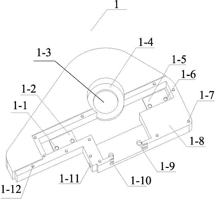
[0058]The housing 1 includes threaded holes I1-1 for the limiting device, mounting bosses I1-2 for the limiting device, bearing mounting surfaces 1-3, gear mounting grooves 1-4, mounting bosses II1-5 for the limiting device, L...

specific Embodiment approach 2

[0077] Specific embodiment 2: The driving method adopts the composite excitation electric signal to realize, the composite excitation electric signal includes the friction control wave and the driving wave, by superimposing the friction control wave on the fast energization stage of the driving wave, the stator is excited in the rapid deformation stage In the state of micro-secondary high-frequency resonance, the frictional resistance between the stator and the rack in the rapid deformation stage is reduced based on the ultrasonic anti-friction effect; the driving wave is a sawtooth wave, and the friction control wave is a sine wave; the period of the sawtooth wave is T 1 , the excitation voltage amplitude is V 1 , the symmetry is S, and the period of the sine wave is T 2 , the excitation voltage amplitude is V 2 , the period ratio of the sawtooth wave to the sine wave is T 1 / T 2 =100~20000, the excitation voltage amplitude ratio is V 1 / V 2 =2~6.

[0078] Working princ...


PUM


Abstract

The invention provides a high-precision stick-slip piezoelectric rotating table and aims to solve the technical problems of small thrust output, low positioning precision, low movement speed, high frictional loss, poor environmental suitability and the like of an existing stick-slip piezoelectric rotating table. The high-precision stick-slip piezoelectric rotating table comprises a casing, a limiting device I, a bearing, a gear, a rotating table, a packaging board, a rack, a limiting device II, a stator, a baffle plate and a packaging casing, wherein thrust and speed of the rotating table areincreased through meshing transmission of the gear and the rack; compared with direct drive of the micro-rotating table, the rotating table is driven to move by rotation of the gear, so that loss produced by rapid friction between a driving element and a rotating shaft is reduced; under different working conditions, positive pressure of the driving element can be adjusted by the table at any time,and output precision and environmental suitability of the rotating table are effectively improved. The high-precision stick-slip piezoelectric rotating table has good application prospect in the fields of precision optical instruments, biological microoperation and micro-nano precise drive and positioning technologies.

Description

technical field [0001] The invention relates to a high-precision piezoelectric stick-slip rotary table, which belongs to the technical field of micro-nano precision driving and positioning. Background technique [0002] Piezoelectric drive technology is a new drive method that uses the inverse piezoelectric effect of piezoelectric materials to convert electrical energy into mechanical energy. Compared with traditional electromagnetic drive methods, it has low speed, high torque (thrust), high torque density, and flexible design. , compact structure, high positioning accuracy, fast response, power-off self-locking, no electromagnetic interference and no electromagnetic interference, no need to use bearings and lubrication, etc., in robot joint drive, precision instrumentation, ultra-precision machining, aerospace and Life science and other fields have broad application prospects, and are one of the hot spots in the field of precision special drive technology in recent years. ...

Claims


Application Information

Patent Timeline
IPC IPC(8): H02N2/12H02N2/14
Inventor 程廷海卢晓晖唐晚静柳虹亮何猛陈鹏飞
Owner CHANGCHUN UNIV OF TECH
Why Eureka
Try Eureka